Production method for glasses lens, marking device, marking system, glasses lens

A technology for spectacle lenses and manufacturing methods, applied in the directions of glasses/goggles, manufacturing tools, instruments, etc., can solve the problems of difficult observation and reduced visibility, and achieve excellent appearance, prevent defective products from leaving the factory, and high energy. Effect

Inactive Publication Date: 2006-08-02
HOYA LENS MFG PHILIPPINES INC
View PDF1 Cites 18 Cited by
  • Summary
  • Abstract
  • Description
  • Claims
  • Application Information

AI Technical Summary

Problems solved by technology

[0006] However, in order to form a mark that does not obstruct the wearer's field of vision, for example, it is necessary to suppress the laser output, reduce the engraving load of the diamond pen, reduce the size of the mark, and form the mark in a shape that is difficult to see. , so that only the marks with reduced visibility can be obtained, but it is not easy to observe when visual recognition is required

Method used


Image

  • Production method for glasses lens, marking device, marking system, glasses lens
  • Production method for glasses lens, marking device, marking system, glasses lens
  • Production method for glasses lens, marking device, marking system, glasses lens

Examples


no. 1 approach

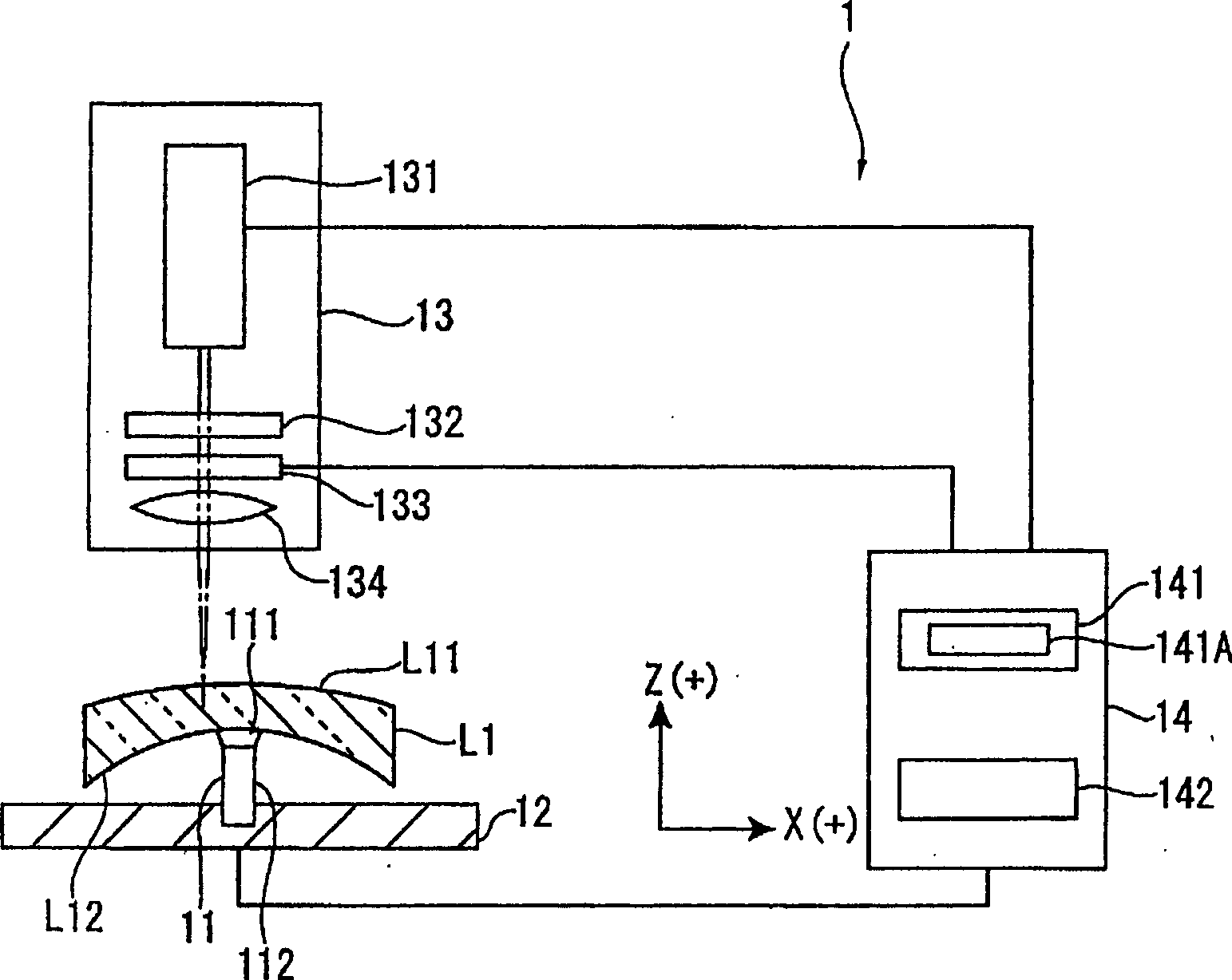
[0087]FIG. 1 is a schematic configuration diagram showing one embodiment of a marking device 1 for spectacle lenses L1 according to the present invention.

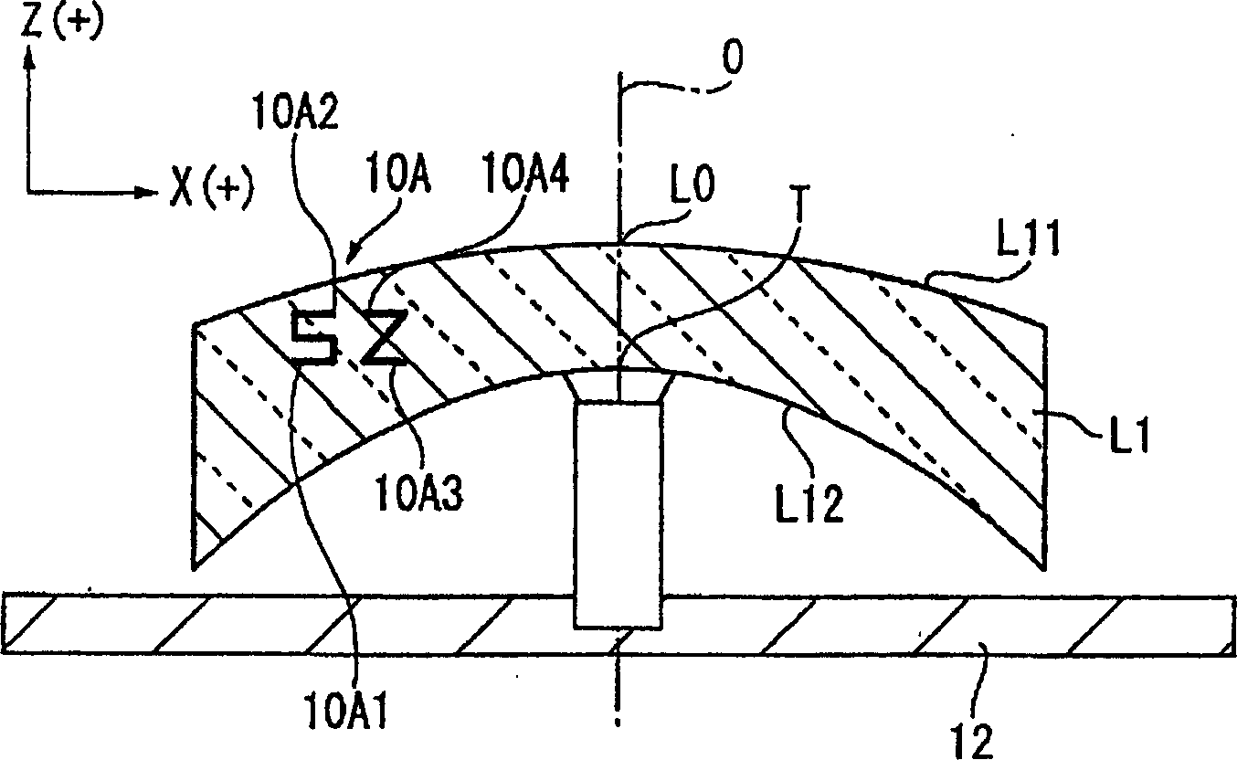
[0088] In this marking device 1 , laser light is condensed inside the spectacle lens L1 to generate a modified portion inside the spectacle lens L1 to form a mark 10A (see FIG. 2 ).

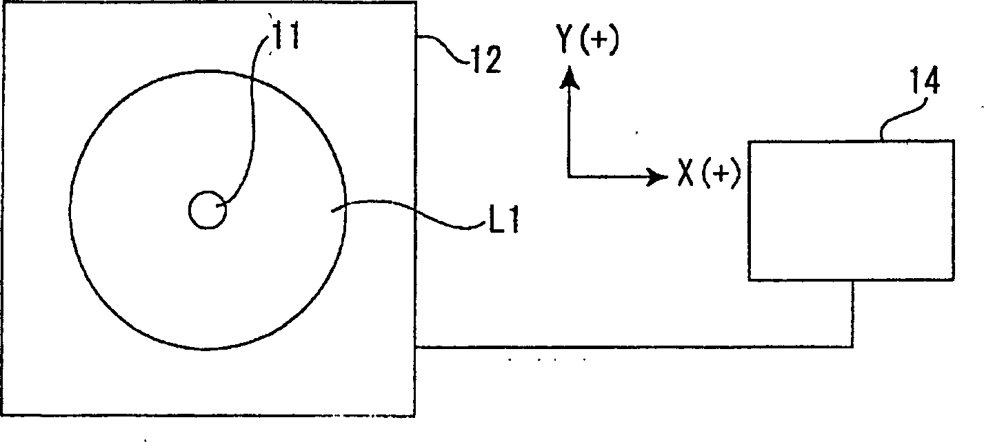
[0089] This marking device 1 has: a holding unit 11 holding the spectacle lens L1; a stage 12 as a moving unit capable of moving the holding unit 11 holding the spectacle lens L1; a laser output unit 13 for emitting laser light; and a control unit 14. .

[0090] The holding part 11 sticks and holds by making the part which contacts the concave surface L12 side of the spectacle lens L1 into a vacuum.

[0091] The holding unit 11 has a suction cup 111 for suctioning the concave surface L12 of the spectacle lens L1 , and a cylindrical portion 112 formed with a vacuum path communicating with the suction cup 111 to vacuum the inside of the suctio...

no. 2 approach

[0125] Below, refer to Figure 3 ~ Figure 11 A second embodiment of the present invention will be described. In the following description, the same reference numerals are attached to the same parts as those already described, and description thereof will be omitted.

[0126] image 3 A spectacle lens L2 having a mark 10B formed therein is shown.

[0127] The spectacle lens L2 of this embodiment is an inner progressive multifocal lens having a spherical or aspheric surface on the convex L11 side (outer side) and a progressive surface on the concave L12 side (inner side).

[0128] The spectacle lens L2 is made of the same material as the spectacle lens L1 of the aforementioned embodiment.

[0129] On the convex surface L11 and the concave surface L12 of the spectacle lens L2, although not shown in the figure, a hard coat film for improving scratch resistance and for preventing reflections such as glare and double images caused by reflection of light is formed. Prevent film e...

no. 3 approach

[0189] refer to Figure 12 to Figure 20 , the third embodiment of the present invention will be described.

[0190] Such as Figure 12 with Figure 13 As shown, the spectacle lens L3 of this embodiment is a spherical lens having a convex surface L11 with a curvature radius of 150 mm, a concave surface L12 with a curvature radius of 150 mm, and a center thickness of 3 mm.

[0191] In the present embodiment, the mark 10C formed inside the spectacle lens L3 is a character such as EP and has a planar structure. When the size of each character is viewed from the X-Y plane, one side W1 is a square of 1.0 mm, and the space W2 between each character is 0.5 mm. This mark 10C is formed at a position 15 mm away from the optical reference position L0 on the convex surface L11 side of the spectacle lens L3 in the X-axis direction ( Figure 12 in W3=15mm). Also, the mark 10C is formed approximately 0.5 mm below the surface of the convex surface L11 of the spectacle lens L3.

[0192] I...


PUM


Abstract

A laser beam is condensed inside a glasses lens (L1) to form a mark (10A). The mark (10A) is formed in a direction almost in parallel to the optical axis of the glasses lens (L1) without obstructing a wearer's view. Positioning is made by allowing the optical reference position (L0) of the glasses lens (L1) to agree with the reference position (T) of a marking device (3), and the glasses lens (L1), after being mounted to the retaing unit (11) of the marking device (3), is positoned based on the optical reference position (L0) of the glasses lens (L1). The glasses lens (L1) is then moved to a marking start position to carry out marking. A pair of hidden marks formed on the glasses lens (L1) are used to adjust the position of the glasses lens (L1), whereby the optical reference position (L0) can be made to agree with the reference position (T) of the marking device (3).

Description

technical field [0001] The present invention relates to a method for manufacturing spectacle lenses, a marking device, a marking system, and spectacle lenses. Background technique [0002] Conventionally, spectacle lenses are provided with marks showing product names and manufacturers, marks to be used as references when framing them in spectacle frames, marks for identifying products during the manufacturing process, and the like. Among them, the mark used in the identification of the manufacturer is not only used for identification, but also used as a mark for the manufacturer to guarantee the quality of the product. [0003] These markings are marked using the following method, that is, as shown in Japanese Patent Laid-Open No. 2000-153698 (pages 1 to 3), engraving with a needle (diamond pen) made of a hard material such as diamond. method, and as shown in Japanese Patent No. 2810151 (pages 1 to 2) and Japanese Patent No. 3081395 (pages 1 to 3), condensing laser light on...

Claims


Application Information

Patent Timeline
Patent Type & Authority Applications(China)
IPC IPC(8): G02C7/02B23K26/00
Inventor 伊藤步泽木大辅
Owner HOYA LENS MFG PHILIPPINES INC
Why Eureka
Try Eureka