Disposable syringe and transfusion system needle head and its production method

A technology of syringes and infusion sets, which is applied in the field of medical equipment, can solve problems such as human hazards, and achieve the effect of reducing injuries and reducing possibilities

Active Publication Date: 2006-08-09
View PDF1 Cites 12 Cited by
  • Summary
  • Abstract
  • Description
  • Claims
  • Application Information

AI Technical Summary

Problems solved by technology

[0004] The purpose of the present invention is to provide a needle for disposable syringes and infusion sets to solve the problem that the needles of the prior art may cut off a piece of skin and flesh tissue that is equivalent to the hole of the needle and inject it into the body, which may cause harm to the human body. problem causing harm

Method used


Image

  • Disposable syringe and transfusion system needle head and its production method
  • Disposable syringe and transfusion system needle head and its production method
  • Disposable syringe and transfusion system needle head and its production method

Examples


Embodiment Construction

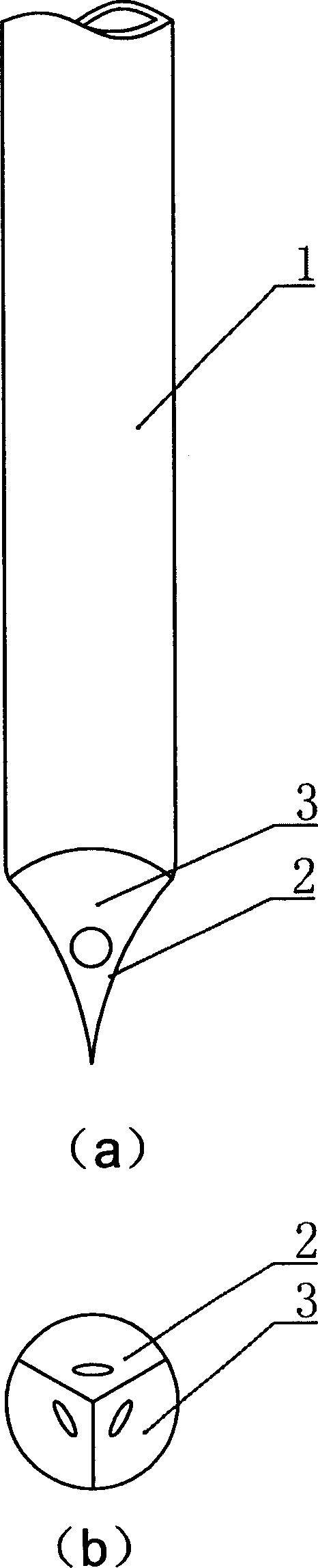
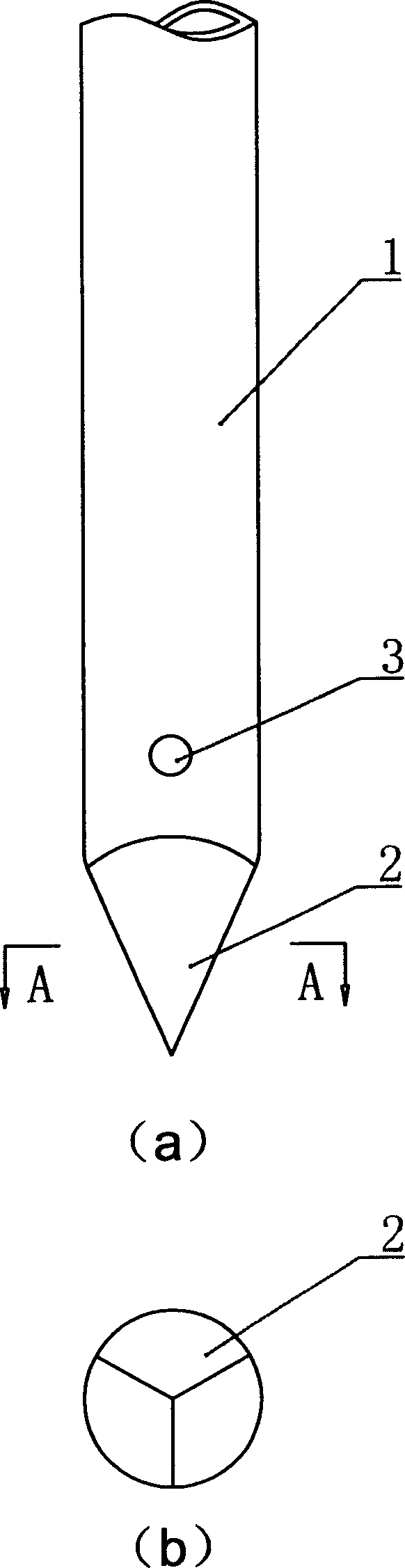
[0022] see figure 1 and figure 2 , the needle head at one end of the tubular needle body 1 of this embodiment is a triangular pyramid, and each cone surface 2 is slightly recessed in the axial direction and the circumference, and each cone surface 2 is provided with a liquid medicine through hole 3 near the tip. (Such as figure 1 shown), from figure 1 b It can be seen that the size of the liquid through hole 3 in the radial direction is very small. The liquid medicine through hole 3 can also be located at the position of the tubular needle body 1 near the needle (such as figure 2 shown).

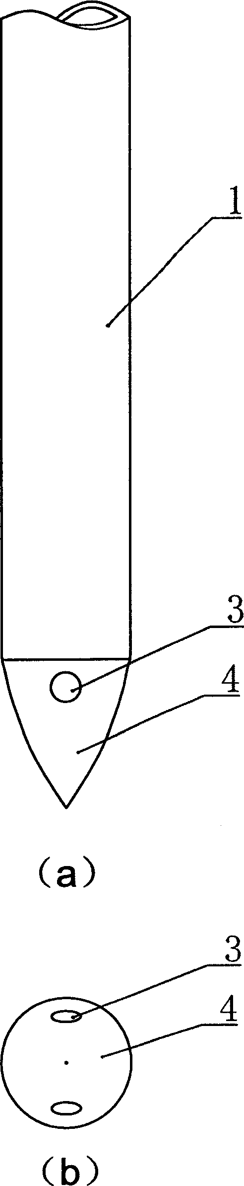
[0023] see image 3 and Figure 4 , the needle head at one end of the tubular needle body 1 of this embodiment is conical, and the conical surface 4 is convex, and two liquid medicine through holes 3 are provided on the conical surface 4 near the tubular needle body 1 (such as image 3 shown). The number of liquid medicine through holes 3 can be increased or decreased according to ...


PUM


Abstract

This invention discloses a one-off injector and pinhead, it includes tubular pin. The pin is made by pyramid type, conic pin, or pyramid and cone. Liquor via holes is set on the pin or other part. The conic pinhead is solid, hollow or part hollow. This invention also discloses the manufacturing method of the pinhead. Because the included angle of foreside of axial backoff conical surface of the conic pin or backside of bulge and axial is small, so the radial size of liquor via hole at corresponding part is small, and the damage of pin to body tissue is greatly reduced. The possible damage of aperture to body is absolutely avoided by set liquor via hole on pipe body near the conic pin. Otherwise, when the pin rotating, damage to body is hard to form, especially the large diameter infusion pin.

Description

technical field [0001] The invention relates to a medical device, in particular to a needle of a disposable syringe and an infusion set and a production method thereof. Background technique [0002] Existing needles for injection generally consist of a tubular needle body and a needle holder connected to one end thereof, and the needle point is formed by cutting and grinding a bevel at the front end of the needle body of a thin-walled tube. The needle point of this form still forms a sharp edge because the inner wall and the inclined surface of the second half of the needle point can cut off the passing skin and flesh tissue. Therefore, when the existing needles for injection are used, a piece of skin and flesh tissue that is equivalent to the inner hole of the needle is cut off and input into the body, which will cause harm to the human body. For intramuscular injection, micropores will be left at the injection site after the needle is withdrawn, and the possibility of inf...

Claims


Application Information

Patent Timeline
Patent Type & Authority Applications(China)
IPC IPC(8): A61M5/158A61M5/32
CPCA61M5/3291B21G1/08A61M5/158A61M5/3286
Inventor 王月安郭玉贤
Why Eureka
Try Eureka