Apparatus and method for compensating for a frequency offset in a wireless communication system

A carrier frequency offset and sampling frequency offset technology, applied in the field of frequency offset equipment, can solve the problem that the receiver cannot recover the transmitted signal, and the receiver cannot accurately synchronize the carrier frequency.

Inactive Publication Date: 2006-08-09
SAMSUNG ELECTRONICS CO LTD
View PDF0 Cites 20 Cited by
  • Summary
  • Abstract
  • Description
  • Claims
  • Application Information

AI Technical Summary

Problems solved by technology

[0015] The first reason is the case where the receiver cannot be precisely synchronized with the carrier frequency generated in the transmitter
The second reason is that the sampling frequency used in the digital-to-analog converter (DAC, Digital-to-Analog Converter) of the transmitter is not precisely synchronized with the sampling frequency used in the DAC of the receiver
Therefore, if the phase change due to carrier frequency offset and the phase change with increasing subcarrier index cannot be accurately estimated and compensated, that is, if the frequency offset cannot be accurately compensated, the receiver will not be able to recover the transmitted signal

Method used


Image

  • Apparatus and method for compensating for a frequency offset in a wireless communication system
  • Apparatus and method for compensating for a frequency offset in a wireless communication system
  • Apparatus and method for compensating for a frequency offset in a wireless communication system

Examples


Embodiment Construction

[0036] Hereinafter, preferred embodiments of the present invention will be described in detail with reference to the accompanying drawings. In the following description of the present invention, the same drawing reference numerals are used for the same elements even in different drawings. Also, detailed descriptions of well-known functions and constructions incorporated herein are omitted when it may obscure the subject matter of the present invention.

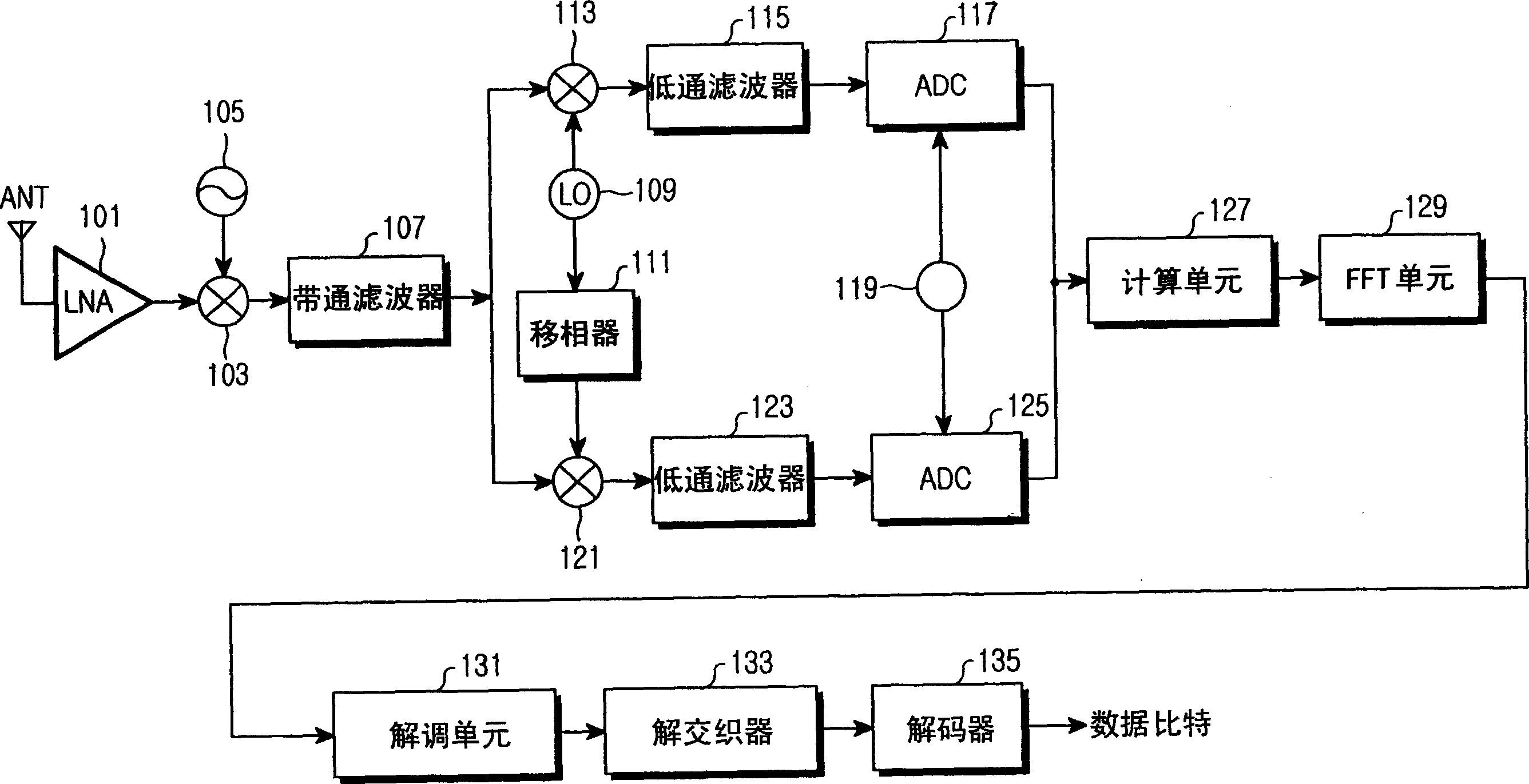
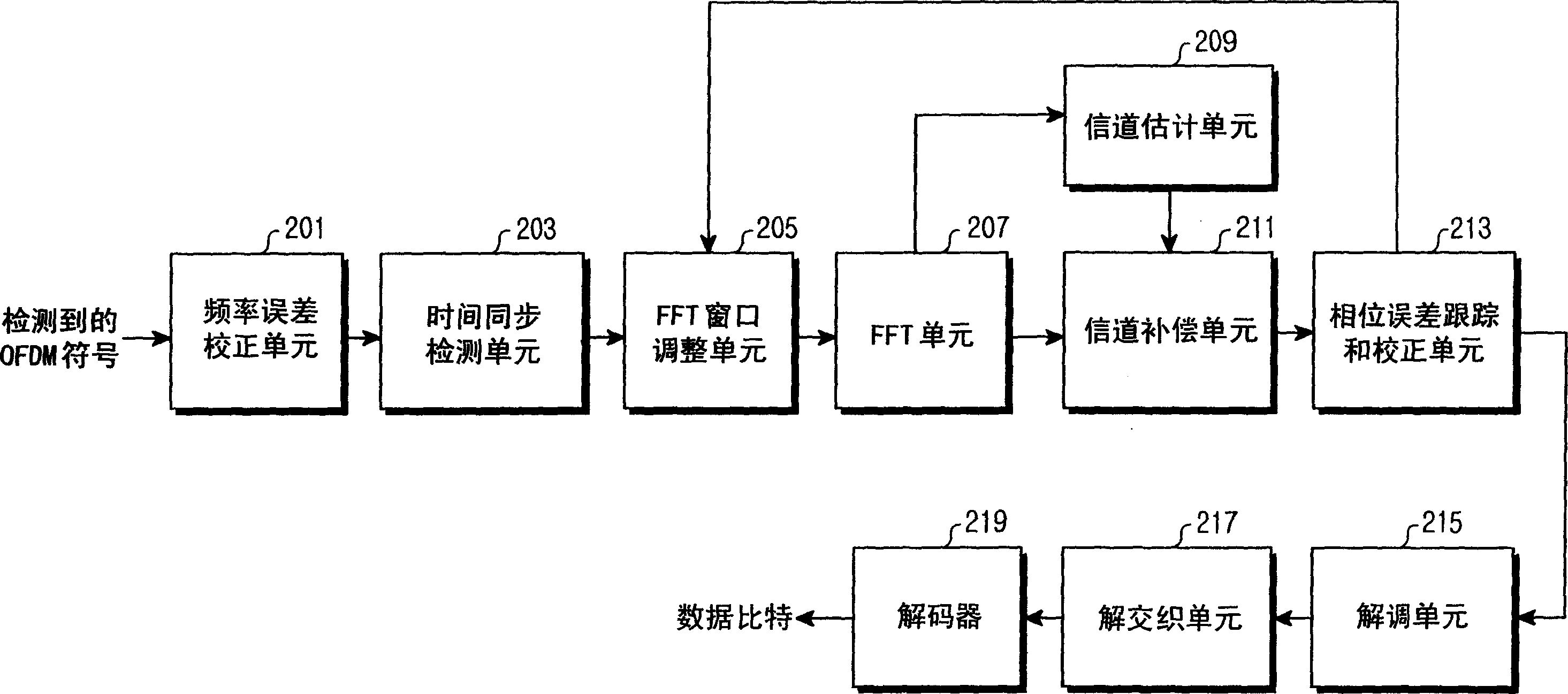
[0037] figure 2 is a block diagram showing the internal structure of a receiver for compensating for frequency offset in an OFDM system according to a preferred embodiment of the present invention. Below, will refer to figure 2 , to explain in detail the structure and operation of the OFDM system receiver according to the present invention.

[0038] exist figure 2 , no longer describe as figure 1 Shown is the radio processing section used to convert RF signals to baseband signals. Although in figure 1 with 2 A packe...


PUM


Abstract

Disclosed is an apparatus and method for compensating for frequency offset in a wireless communication system using an OFDM system which can compensate for phase change due to carrier frequency offset and sampling frequency offset of data carried on subcarriers. The apparatus includes an FFT window adjustment unit for receiving sampling data when a packet is received, setting a start point of a FFT window at a start point of long training symbols and adjusting a position of the FFT window according to an input window adjustment value, an FFT unit for receiving an output of the FFT window adjustment unit, transforming time-domain symbols into frequency-domain symbols and calculating FFT coefficients, a channel estimation unit for receiving the coefficients from the FFT unit, estimating a channel state and outputting a value for compensating for an estimated value, a channel compensation unit for compensating for the frequency-domain symbols using the output of the channel estimation unit and a phase error tracking and correction unit for receiving an output of the channel compensation unit, detecting a sampling frequency offset and a phase change of a carrier signal and outputting the window adjustment value to the FFT window adjustment unit.

Description

technical field [0001] The present invention relates to a device and method for compensating for frequency offset in a wireless communication system, and more particularly, to a method for compensating for wireless communication using an Orthogonal Frequency Division Multiplexing (OFDM, Orthogonal Frequency Division Multiplexing) system Apparatus and method for frequency offset in a system. Background technique [0002] Wireless communication systems transmit data using designated frequencies. Wireless communication systems have been classified into various types of wireless communication systems. A representative of the wireless communication system is a mobile communication system, which is briefly classified into a synchronous type mobile communication system and an asynchronous type mobile communication system. In addition, a system based on the Institute of Electrical and Electronics Engineers (IEEE) 802.11 standard has been proposed as a system in which fixed termina...

Claims


Application Information

Patent Timeline
Patent Type & Authority Applications(China)
IPC IPC(8): H04L27/26
CPCH04L27/2657H04L27/2665H04L27/2695H04L27/2675B32B5/022B32B7/12B32B21/042B32B21/10B32B21/14B32B2419/04E04F15/042
Inventor 高成润尹勉基朴柱龙宋学勋
Owner SAMSUNG ELECTRONICS CO LTD
Why Eureka
Try Eureka