
High dynamic scope quick clock recovery system based on voltage crystal oscillator

A technology of voltage-controlled crystal oscillation and large dynamic range, applied in transmission systems, digital transmission systems, automatic power control, etc., can solve the problem of increasing the time delay of the carrier synchronization loop and reducing the resistance of the clock recovery system to large sampling frequency offsets Capability and other issues, to achieve the effect of clock recovery, reduce loop delay and operating frequency, reduce hardware complexity and hardware cost

Inactive Publication Date: 2008-04-30
BEIJING SATELLITE INFORMATION ENG RES INST
View PDF0 Cites 10 Cited by
  • Summary
  • Abstract
  • Description
  • Claims
  • Application Information

AI Technical Summary

Problems solved by technology

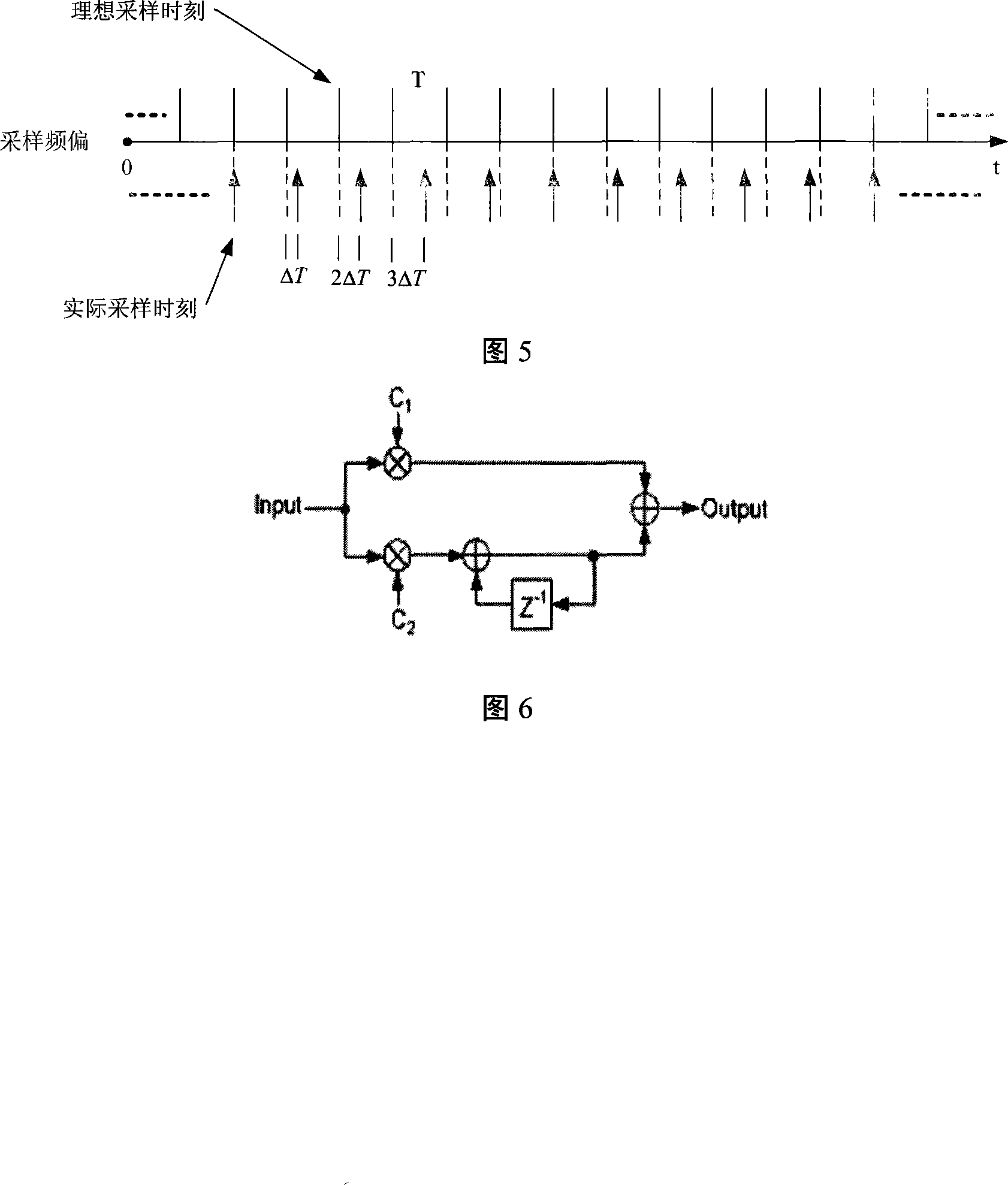
In (1) and (2), the phase detection process is generally carried out inside the carrier synchronization loop. This structure increases the time delay of the carrier synchronization loop, reduces the ability of the clock recovery system to resist large sampling frequency offsets, and Make most of the operations in demodulation be at high speed

Method used


Image

  • High dynamic scope quick clock recovery system based on voltage crystal oscillator
  • High dynamic scope quick clock recovery system based on voltage crystal oscillator
  • High dynamic scope quick clock recovery system based on voltage crystal oscillator

Examples


Embodiment Construction

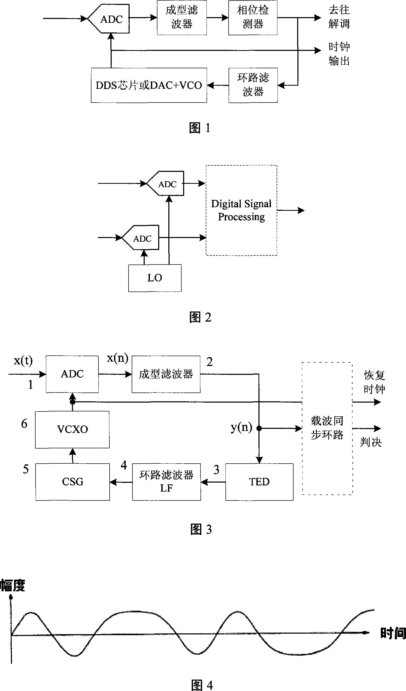
[0025] As shown in Fig. 3, the present invention is suitable for realization on FPGA or DSP+FPGA platform. If implemented by FPGA, except the two modules of ADC and VCXO in Figure 3, other modules are implemented in FPGA; if implemented by DSP+FPGA, the timing error detector TED in Figure 3 can be implemented in DSP, other Modules except ADC and VCXO are implemented in FPGA. The shaping filter adopts the root raised cosine filter (Root Raised Cosine Filter, RRCF); the voltage-controlled crystal oscillator VXCO adopts a general-purpose voltage-controlled crystal oscillator, which includes four pins: the input control signal pin, the power pin , ground pin and output clock signal pin.

[0026] As shown in Figure 3, the working process of the clock recovery loop is: (1) the root raised cosine filter (RootRaised Cosine Filter, RRCF) performs shaping filtering on the sampling signal of the ADC to restore the best sampling point; (2) timing The error detector (Timing Error Detecto...


PUM


Abstract

A fast clock recovery system with a large dynamic range based on a voltage-controlled crystal oscillator, the clock recovery system is placed before a carrier synchronization loop, and includes: an analog-to-digital conversion ADC, a shaping filter, a timing error detector TED, Loop filter LF, control signal generator CSG, voltage controlled crystal oscillator VCXO, among which TED calculates the phase detection error signal P value according to the output data of the shaping filter, and then performs two consecutive phase detection error signal P values. Differential processing, multiply the multiplication factor and the differential processing result, and send the multiplication result to the loop filter LF until the sampling frequency offset is captured, and finally send the phase detection error signal P value to the loop filter LF to achieve Sampling frequency offset tracking. After continuous correction of the loop, the oscillation frequency of the VCXO is finally locked with the sampling clock of the transmitter to realize clock recovery. The invention has the advantages of wide dynamic range and fast clock recovery.

Description

technical field [0001] The invention relates to a clock recovery system for communication signals, in particular to a clock recovery system using an analog-digital hybrid mode based on a voltage-controlled crystal oscillator (VCXO). Background technique [0002] In a communication system, the clock mismatch between the transmitting end and the receiving end will cause inter-symbol interference (Inter-symbol Interference, ISI) in the demodulation of the receiver, and seriously degrade the system performance, so the clock recovery must be completed at the receiving end , to eliminate or mitigate ISI. The principle of clock recovery is to firstly extract timing information from a received signal, and then use the timing information to regenerate a sampling clock or sampling data, thereby realizing clock recovery. There are three main ways of clock recovery: analog mode, analog-digital hybrid mode (as shown in Figure 1), and digital mode (as shown in Figure 2). The analog mode...

Claims


Application Information

Patent Timeline
IPC IPC(8): H04L7/027H03L7/08
Inventor 王梦源尹浩琼邹光南刘大禹
Owner BEIJING SATELLITE INFORMATION ENG RES INST
Learn More