

Alarming transmission device for syring inaccurate installation
A transmission device and syringe technology, applied in the field of medical devices, can solve the problems of increasing the risk of micro-injection, self-propelling of the syringe push rod, backflow of patients' blood, etc., and achieve the effects of reducing medical accidents, reliable transmission, and reducing risks
- Summary
- Abstract
- Description
- Claims
- Application Information
AI Technical Summary
Problems solved by technology
Method used
Image

Examples
Embodiment 1
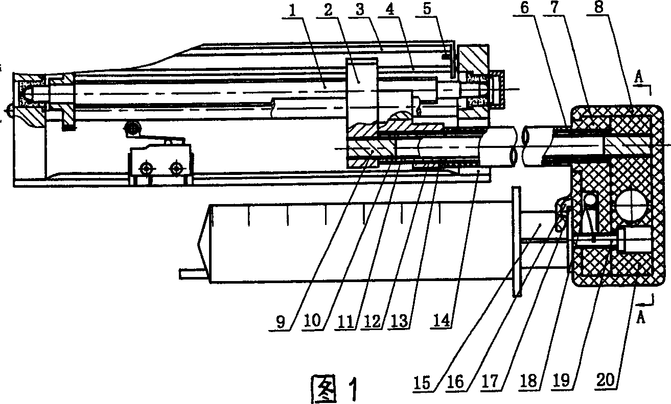
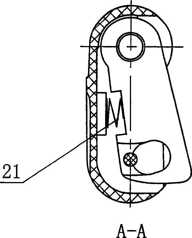
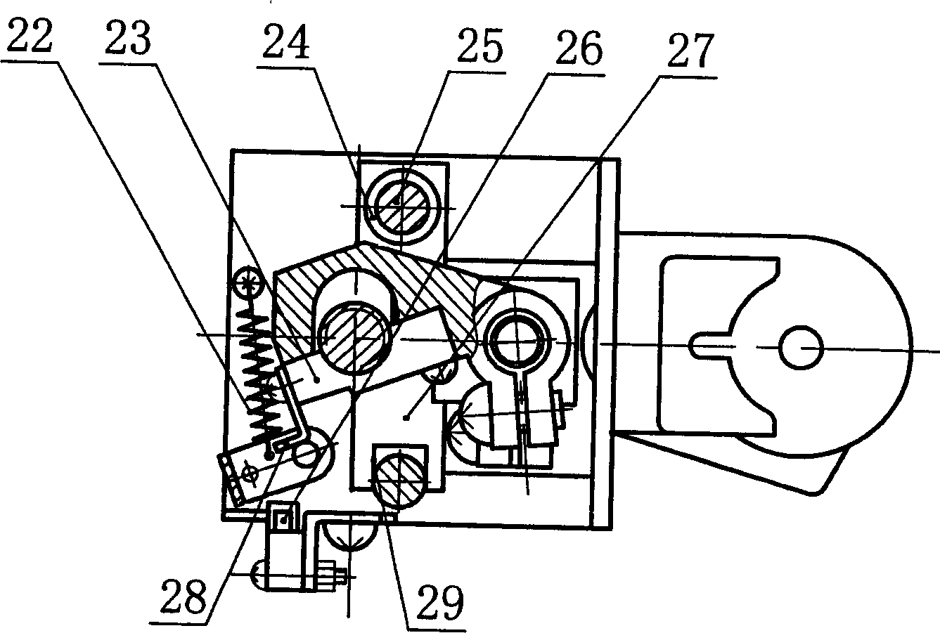
[0016] Referring to Figures 1-3, the present invention consists of a screw rod 1, a nut clutch seat 2, a swing frame 3, a pole 4, a positioning pin 5, a push rod sheath 6, a push head 7, a push head sheath 8, a plunger 9, Cover 10, swing rod 11, push rod 12, clip seat 13, frame 14, syringe push rod 15, push piece slot 16, push piece 17, dial spring 18, safety pin 19, pendulum block 20, pressure spring 21, Extension spring 22, opening and closing nut 23, sliding sleeve 24, guide slide bar 25, sensing element 26, slide seat 27, contact 28, chute 29 are formed, and two guide slide bars 25 are fastened on the frame 14, Two guide rails 25 pass through the chute 29 on the sliding sleeve 24 and the sliding seat 27 respectively, the sliding sleeve 24 is fixed on the sliding seat 27, and the sliding sleeve 24 and the guiding sliding rod 25 are moving fits, and the sliding seat 27 can The sliding sleeve 24 and the chute 29 can freely translate on the two guide rods 25, and the clamping ...
Embodiment 2
[0018] Transmission mode of the present invention is as follows:
[0019] See Fig. 1-3, (1) The opening and closing nut 23 is separated from the screw rod 1 and installed: pinch the pendulum block 20 and the push head sheath 8, the compression spring 21 is in a compressed state, the pendulum member rotates at a certain angle, and the opening and closing The nut 23 is separated from the screw rod 1, the contact 28 pushes the pendulum 3 to rotate at a certain angle around the two positioning pins 5, and the sensing element 26 converts the swing of the pendulum 3 into a potential signal and transmits it to the electrical signal processing system. The tension spring 22 is in a stretched state, the elastic force of the dial spring 18 is released, the safety pin 19 is ejected under the elastic force of the dial spring 18, the relative position of the swing bar member and the push rod member is locked, and the swing bar member and the push rod member become a whole Can be freely tran...
Embodiment 3
[0022] The working mode of the present invention is as follows:
[0023] 1. The relative position locking state of the swing rod member and the push rod member: For the positional relationship between the safety pin 19 and the pendulum block 20 under the relative position lock state of the swing rod member and the push rod member, see Figure 4 , Figure 5 . In the locked state of the relative position of the swing rod member and the push rod member, if the pump starts, the alarm system will send out an alarm signal; in the locked state of the relative position of the swing rod member and the push rod member, the swing rod member and the push rod member are integrated It can be freely translated in the longitudinal direction so as to snap the push piece 17 into the push piece slot 16 .
[0024] 2. The state of the relative position locking release of the swing rod member and the push rod member: the positional relationship between the safety pin 19 and the pendulum block 20 ...
PUM
 Abstract
Description
Claims
Application Information