Liquid-liquid extraction method

An extraction and extraction agent technology, applied in the field of liquid-liquid extraction, can solve problems such as difficult implementation and no extraction device

Active Publication Date: 2006-08-16
MITSUI CHEM INC
View PDF1 Cites 11 Cited by
  • Summary
  • Abstract
  • Description
  • Claims
  • Application Information

AI Technical Summary

Problems solved by technology

[0009] However, as disclosed in Japanese Patent No. 2899927 (Patent Document 1), the method for extracting contained p-toluic acid from waste water produced by a terephthalic acid manufacturing device with p-xylene has no cheap extraction device. and difficult to implement commercially

Method used


Image

  • Liquid-liquid extraction method

Examples


Embodiment 1

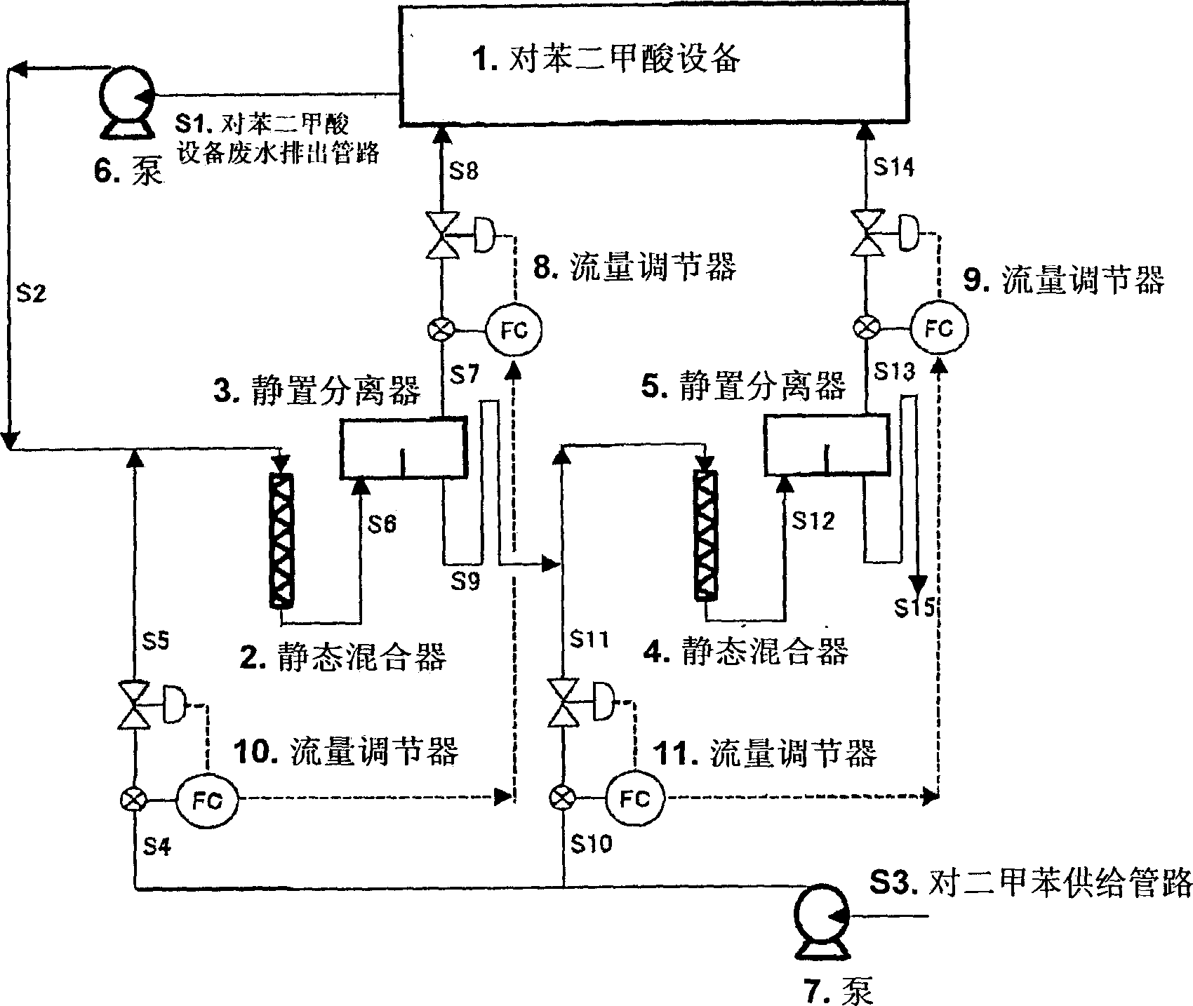
[0058] figure 1 A schematic diagram illustrating an embodiment of the present invention. The waste water from the terephthalic acid plant 1 flows through the waste water discharge line S1, the pressure is raised to 0.6 MPa-G by the pump 6, and mixed with the p-xylene from the supply line S5 at the static mixer 2. The p-xylene from the supply pipeline S5 is to flow through the supply pipeline S3, use the pump 7 to raise the pressure to 0.7MPa-G, and use the flow regulator 10 to adjust the flow rate to be 4 parts by weight of waste water: 1 part by weight of p-xylene . The static mixer 2 is a product of NORITAKE, the number of elements for changing the flow direction is 12, and the stagnation time is 15 seconds.

[0059] The liquid mixed by the static mixer 2 flows through the supply line S6 and is supplied from the lower part of the static separator 3 . The p-xylene after liquid-liquid separation flows through the outlet pipeline S7, and the flow rate is adjusted by the flow...


PUM


Abstract

The invention provides a method, with which large liquid flow stream of liquid-liquid extraction is performed efficiently and easily in a wide operating range, and particularly, to provide a suitable method to extracting useful substance from over 50 t / hr of wastewater, which is generated from a device that produces high-purity terephthalic acid. In a liquid-liquid extracting method of the invention, wastewater and extractant, which is used to extract a target ingredient from the wastewater, are flowed into a pipe having a structure in which the wastewater and the extractant are mixed, to be mixed with each other, a mixed liquid is supplied to a container while being decelerated by gravity, and the mixed liquid stands so as to be liquid-liquid extracted.

Description

technical field [0001] The present invention relates to a liquid-liquid extraction method for extracting target components from waste water with a large flow rate of, for example, more than 50 tons per hour (t / hr). Background technique [0002] When the concentration of useful substances in wastewater is low, the economic benefits of recycling are poor, so they are usually discharged after being treated with activated sludge. For example, wastewater from a high-purity terephthalic acid production facility, although containing a large amount of p-toluic acid as a reaction intermediate, is usually treated with activated sludge because of its low concentration. [0003] However, when activated sludge treatment is used, not only the loss of useful substances is caused, but also a large amount of energy such as electric energy for operation is consumed. Moreover, it is also a cause of bad odor. With the increase in the size of terephthalic acid production facilities, the amount...

Claims


Application Information

Patent Timeline
IPC IPC(8): B01D11/04C02F1/26
CPCE02D5/223E02D5/28E02D27/12
Inventor 中尾藤正上村义明村井隆信山本大祐
Owner MITSUI CHEM INC
Why Eureka
Try Eureka