Ink jet printer with ink-path and method for forming ink path

A technology of inkjet printers and ink channels, which is applied in printing and other directions, and can solve problems such as a large number of components and complexity

Inactive Publication Date: 2006-08-23
BROTHER KOGYO KK
View PDF1 Cites 4 Cited by
  • Summary
  • Abstract
  • Description
  • Claims
  • Application Information

AI Technical Summary

Problems solved by technology

Although the disclosed connection structure provides an airtight and secure connection between the components forming the ink channels, it is rather complex and requires a large number of components

Method used


Image

  • Ink jet printer with ink-path and method for forming ink path
  • Ink jet printer with ink-path and method for forming ink path
  • Ink jet printer with ink-path and method for forming ink path

Examples


Embodiment Construction

[0029] An embodiment of the present invention is described below in conjunction with the accompanying drawings.

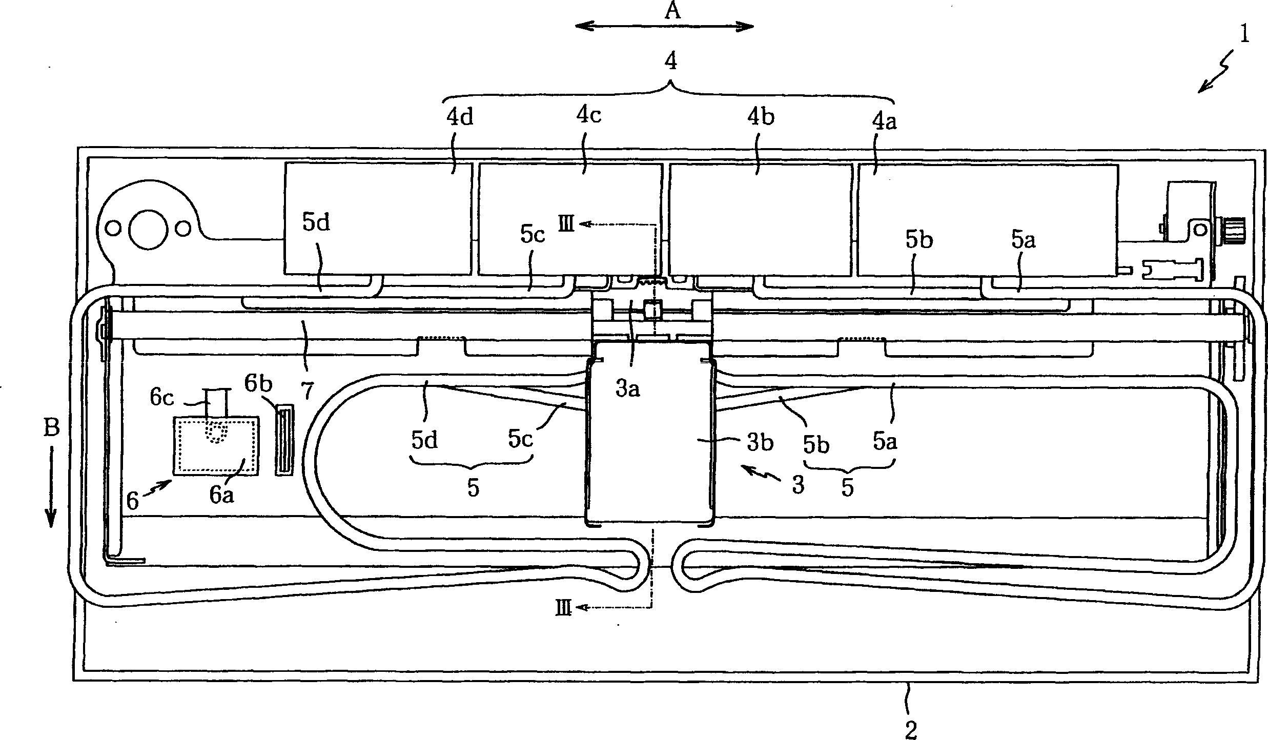
[0030] figure 1 is a plan view showing the internal structure of the ink jet printer 1 of an embodiment of the present invention. The inkjet printer 1 includes in its main frame 2: a print head unit 3 that ejects ink onto a sheet of paper; an ink tank 4 that stores ink to supply ink to the print head unit 3; A tank 4 is supplied to a pipe 5 of the print head unit 3; a return unit 6 and a paper feeder for supplying paper.

[0031] The main frame 2 is basically box-shaped and made of flame-retardant plastic. A guide bar 7 is horizontally provided in the longitudinal direction of the main frame 2, and supports the print head unit 3 so that the print head unit 3 is in the direction A perpendicular to the paper feeding direction B (in figure 1 Left and right direction) reciprocating movement.

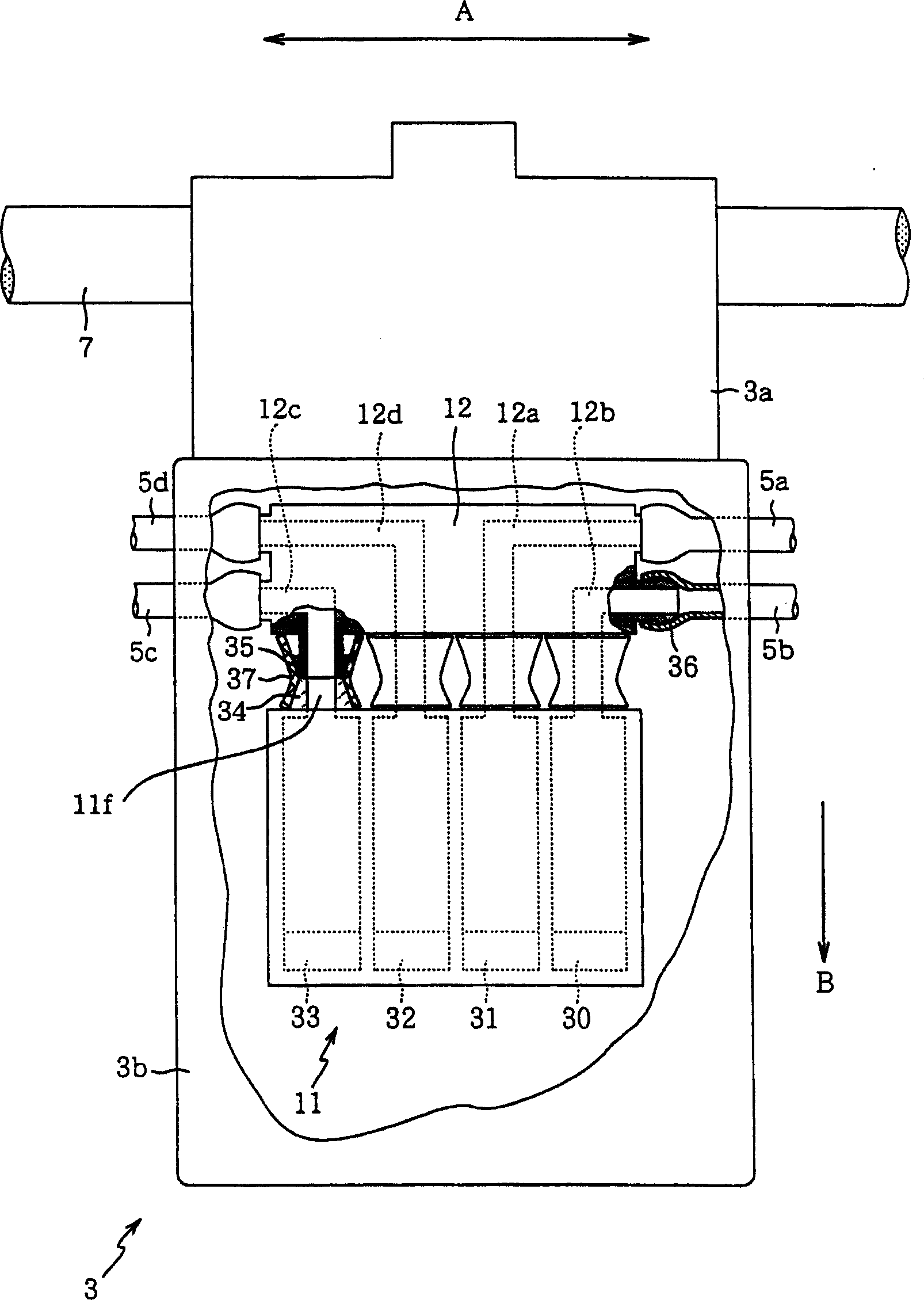
[0032] The print head unit 3 is substantially box-shaped, and includes a...


PUM


Abstract

An ink path through which ink is delivered from an ink source to a printhead unit includes an ink tube and a joint. The ink tube has a first layer formed of a material with low vapor and gas permeability and a second layer radially thicker than the first layer and formed of a flexible material. The joint has a maximum-diameter portion whose outer diameter is larger than an inner diameter of the ink tube. The joint is inserted into the ink tube. Further, a locking member is fitted over the ink tube. The locking member has an inner-diameter portion whose inner diameter is smaller than an outer diameter of a connection between the maximum-diameter portion of the joint and the ink tube.

Description

[0001] This case is a divisional application of a patent application titled "Inkjet Printer with Ink Channels and Method for Forming Ink Channels", filed on September 11, 2002, and numbered "02142617.1". technical field [0002] The present invention relates to an ink jet printer, and more particularly to an ink jet printer having ink channels formed by components which are positively and hermetically interconnected. The invention also relates to methods of forming such ink channels. Background technique [0003] Inkjet printers are known that employ an ink supply system using tubes. This type of inkjet printer has: a print head that ejects ink onto a print medium; a carriage that mounts the print head; an ink tank that is mounted outside the carriage to store ink; and, an ink tank that supplies ink to the print head the pipe. One end of the tube is connected to a stationary ink tank, and the other end is connected to a printhead that reciprocates along the print medium wi...

Claims


Application Information

Patent Timeline
Patent Type & Authority Applications(China)
IPC IPC(8): B41J2/175B41J2/18
Inventor 加贺光臼井孝正
Owner BROTHER KOGYO KK
Why Eureka
Try Eureka