Automatic detecting and compensating circuit for single and double lamps

A detection circuit and automatic detection technology, applied in the direction of electric light sources, electrical components, lighting devices, etc., can solve problems such as differences, incompatible sensitivity of protection signals, etc.

Active Publication Date: 2006-08-23
DONGYANG TOSPO LIGHTING
View PDF0 Cites 2 Cited by
  • Summary
  • Abstract
  • Description
  • Claims
  • Application Information

AI Technical Summary

Problems solved by technology

[0004] What the present invention aims to solve is to overcome the incompatibility of protection signals and sensitivity differences caused by load changes in the prior art due to the use of fixed load mode design, and aims to provide an automatic detection and compensation circuit for single and double lamps, thereby realizing electronic ballasting. The automatic compensation function of the current converter to protect the signal under different load conditions

Method used


Image

  • Automatic detecting and compensating circuit for single and double lamps
  • Automatic detecting and compensating circuit for single and double lamps
  • Automatic detecting and compensating circuit for single and double lamps

Examples


Embodiment 1

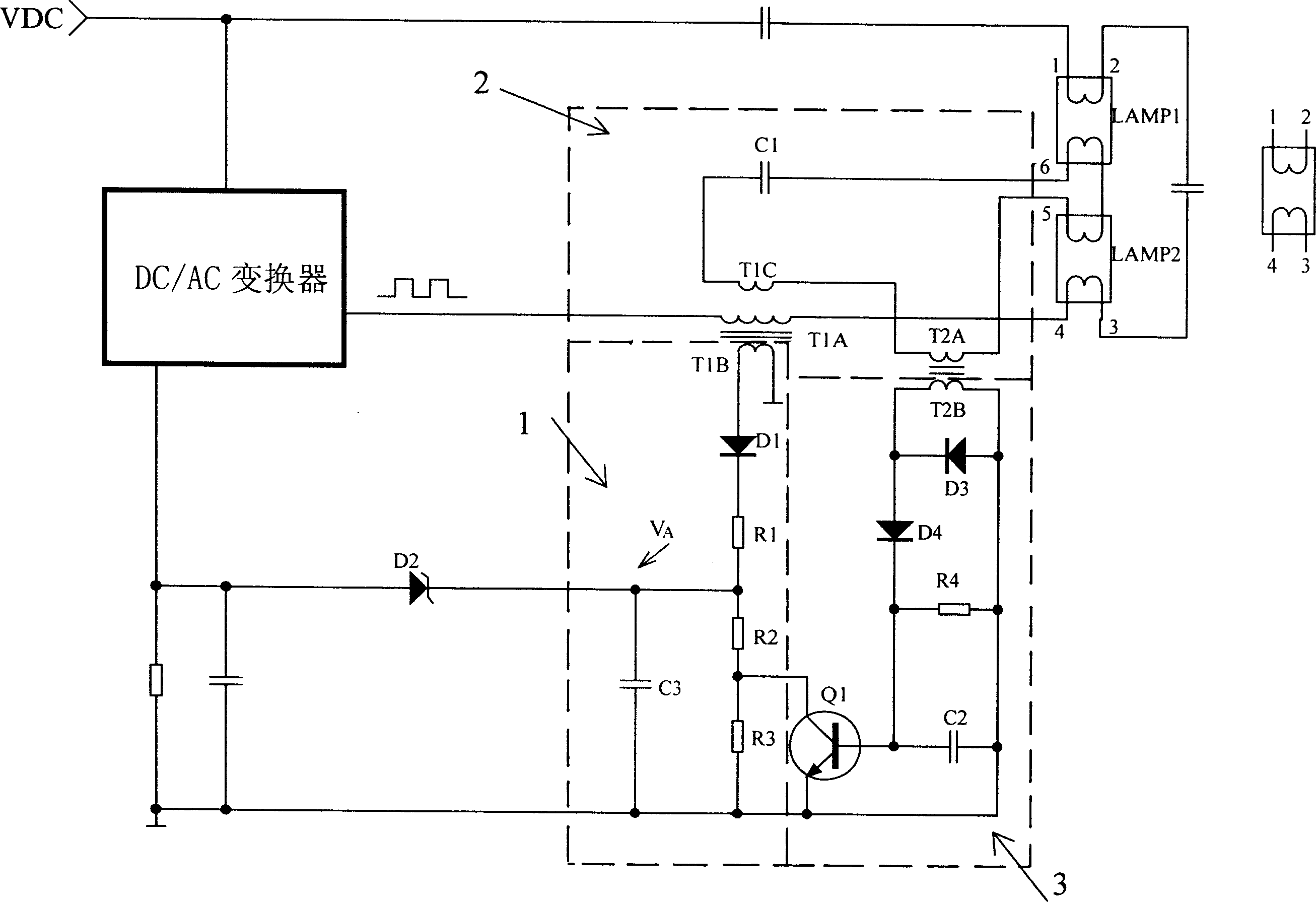
[0017] see figure 2 , outside the virtual frame is a typical electronic ballast circuit, including DC / AC converter (including abnormal protection execution circuit), output circuit and fluorescent tube circuit, between the DC / AC converter, output circuit and fluorescent tube circuit , increasing the single and double lamp automatic detection compensation circuit of the present invention (the circuit in the dashed frame). The single and double lamp automatic detection compensation circuit is composed of abnormal signal detection circuit 1, single and double lamp detection circuit 2 and single and double lamp control circuit 3, and its abnormal protection signal is taken from the secondary winding T of the output inductor 1B , and its specific circuit structure is: an output inductor and three windings T 1A , T 1B , T 1C , three rectifier diodes D 1 、D 3 、D 4 , a current limiting resistor R 1 , two compensating resistors R 2 , R 3 , a current sensor T 2 Two windings T...

Embodiment 2

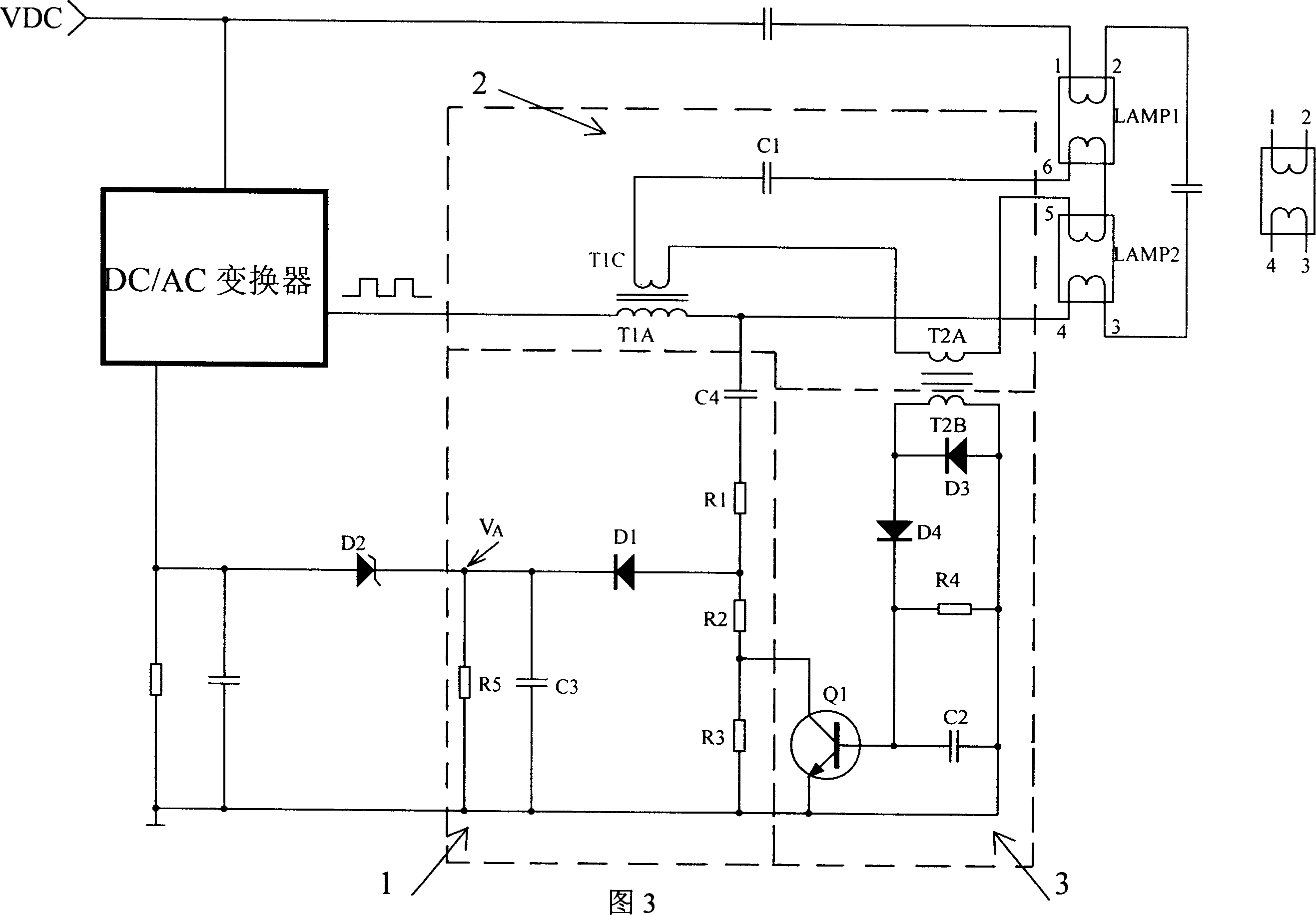
[0020] Referring to Fig. 3, the electronic ballast circuit of this embodiment is the same as the previous embodiment, and the single and double lamp automatic detection compensation circuit of the present invention is inside the virtual frame; the single and double lamp automatic detection compensation circuit is also composed of the abnormal signal detection circuit 1 , single and double lamp detection circuit 2 and single and double lamp control circuit 3, the abnormal protection signal is taken from the main winding T of the output inductor 1A The common end of the terminal and the 4 pins of the fluorescent lamp circuit is composed of: an output inductor and two windings T 1A , T 1C , three rectifier diodes D 1 、D 3 、D 4 , a current limiting resistor R 1 , two compensating resistors R 2 , R 3 , a current transformer T 2 Two windings T 2A , T 2B , a control transistor Q 1 , a filter resistor R 4 and a filter capacitor C 2 , a filament current limiting capacitor C...


PUM


Abstract

Present invention discloses a single double lamp automatic-detection compensation circuit for fluorescent lamp electronic ballast. It includes abnormal signal detection abnormal signal detection circuit, single double lamp detection circuit single double lamp control circuit, wherein lamp detection circuit connected to filament leading out end, single double lamp control circuit receiving single double lamp detection circuit signal and outputting control signal, abnormal signal detection circuit set between electronic ballast output circuit and DC / AC convertor and receiving single double lamp control circuit control signal and in lamp tube disorder working outputting steady disorder signal protection voltage V to DC / AC convertor. Said invention can effectively solves guard signal compatibility problem in current technology and sensitivity problem to realize guard signal automatically compensating function in lamp tube disorder working or different loading condition.

Description

technical field [0001] The invention relates to the field of control technology in power electronics and lighting electronics, in particular to the abnormal signal compensation technology of electronic ballasts for fluorescent lamps. Background technique [0002] In the application technology of electronic ballasts for fluorescent lamps composed of half-bridge series resonant circuits, there are abnormal protection circuits to ensure that the electronic ballasts will not be damaged when the fluorescent tubes are abnormal. [0003] The abnormal protection signal generation circuit in the prior art is designed in a fixed load mode ( figure 1 In the dashed box), although when the load is abnormal, the secondary winding T of the primary circuit output inductance 1B The collected AC voltage signal is rectified and delayed and filtered to generate an abnormal protection signal voltage V A , breakout diode D 2 The voltage threshold is used to stop the oscillating output of the D...

Claims


Application Information

Patent Timeline
Patent Type & Authority Applications(China)
IPC IPC(8): H05B41/298H05B41/14
Inventor 曾浩然
Owner DONGYANG TOSPO LIGHTING
Why Eureka
Try Eureka