Scroll compressor

A scroll compressor and scroll technology, applied in the direction of rotary piston machinery, rotary piston pump, mechanical equipment, etc., can solve problems such as increased contact surface pressure, adhesion, compressor compression efficiency, and reduced durability. Achieve the effect of eliminating adhesion, high reliability and low cost

Active Publication Date: 2006-08-23
PANASONIC CORP
View PDF3 Cites 7 Cited by
  • Summary
  • Abstract
  • Description
  • Claims
  • Application Information

AI Technical Summary

Problems solved by technology

[0027] In addition, in the scroll compressor described in Patent Document 2, considering the compression chambers formed between the fixed scroll member and the orbiting scroll member, the compression heat generated by the compression action makes each coil Thermal expansion of the body without considering the deformation of the fixed scroll and orbiting scroll due to the pressure difference between the discharge pressure and the suction pressure of the compressor
Especially in the shell part of the eccentric bearing in the orbiting scroll, the thickness of the mirror plate of the orbiting scroll is small, and due to the pressure difference between the discharge pressure and the suction pressure, the deformation to the side of the fixed scroll becomes large, and the orbiting scroll Since the tooth bottom of the scroll and the tooth tip of the fixed scroll do not fully contact, the contact surface pressure increases, mutual adhesion occurs, and there is a problem that the compression efficiency and durability of the compressor are reduced.

Method used


Image

  • Scroll compressor
  • Scroll compressor
  • Scroll compressor

Examples


Embodiment 1

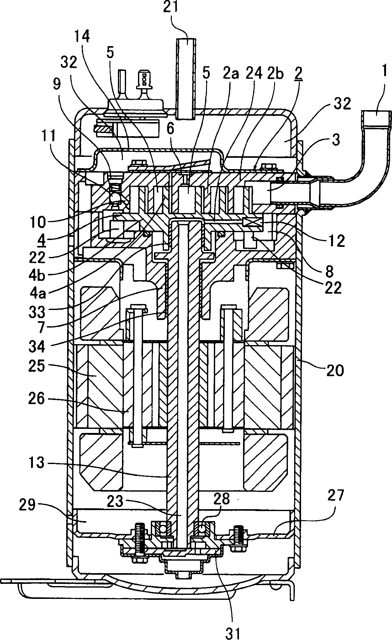
[0090] figure 1 It is a longitudinal sectional view showing the scroll compressor according to the first embodiment of the present invention. In addition, in the scroll compressor of the first embodiment shown in the figure, for Figure 17 In the illustrated conventional scroll compressors, the same functions are denoted by the same reference numerals.

[0091] The scroll compressor of this embodiment has a compression mechanism part and a motor mechanism part in the hermetic container 20 . The compression mechanism part is arranged above the airtight container 20, and the motor mechanism part is arranged below the compression mechanism part. In the upper part of the airtight container 20, a suction pipe 1 and a discharge pipe 21 are provided. In the lower part of the airtight container 20, there is an oil storage container 29 for storing lubricating oil.

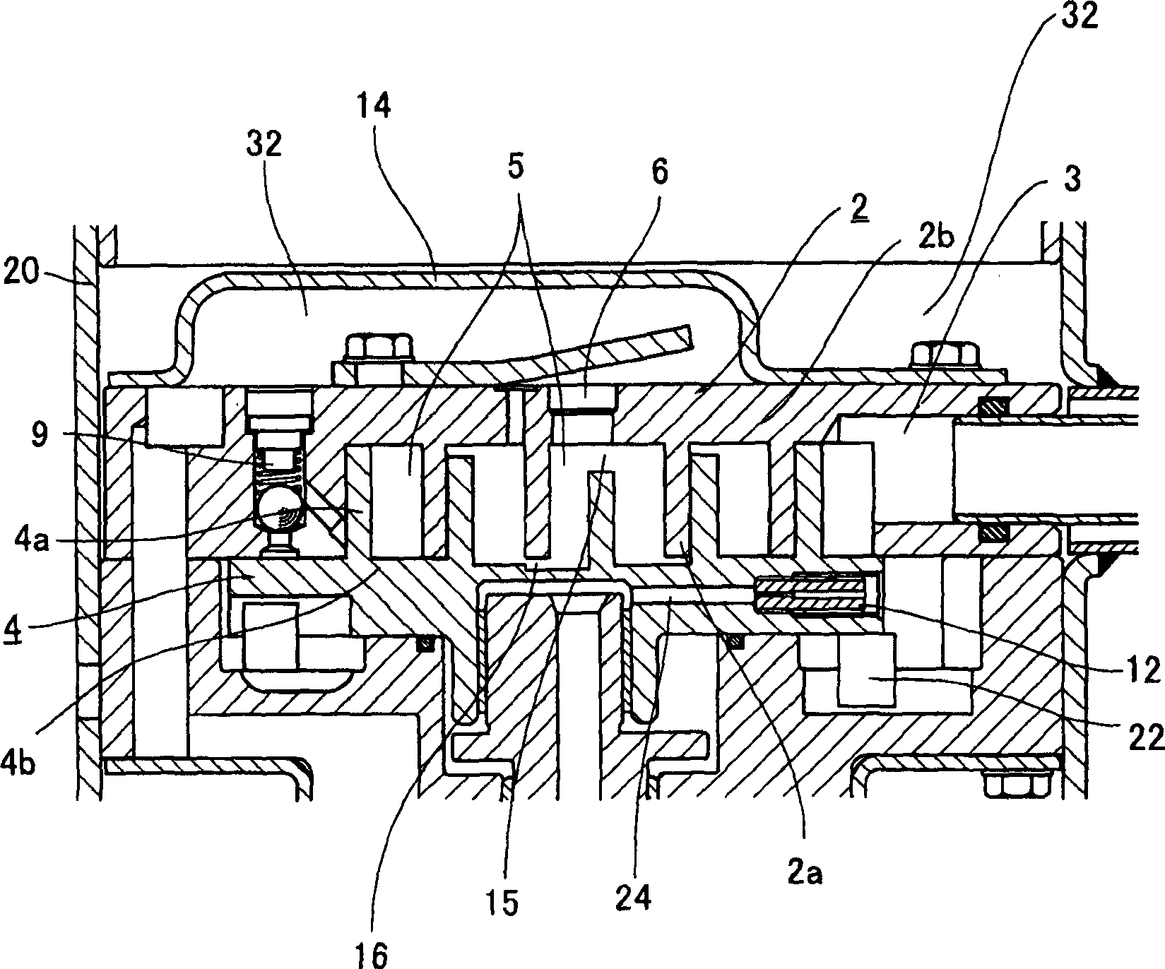
[0092] The compression mechanism part is composed of a fixed scroll member 2 and an orbiting scroll member 4 , and th...

Embodiment 2

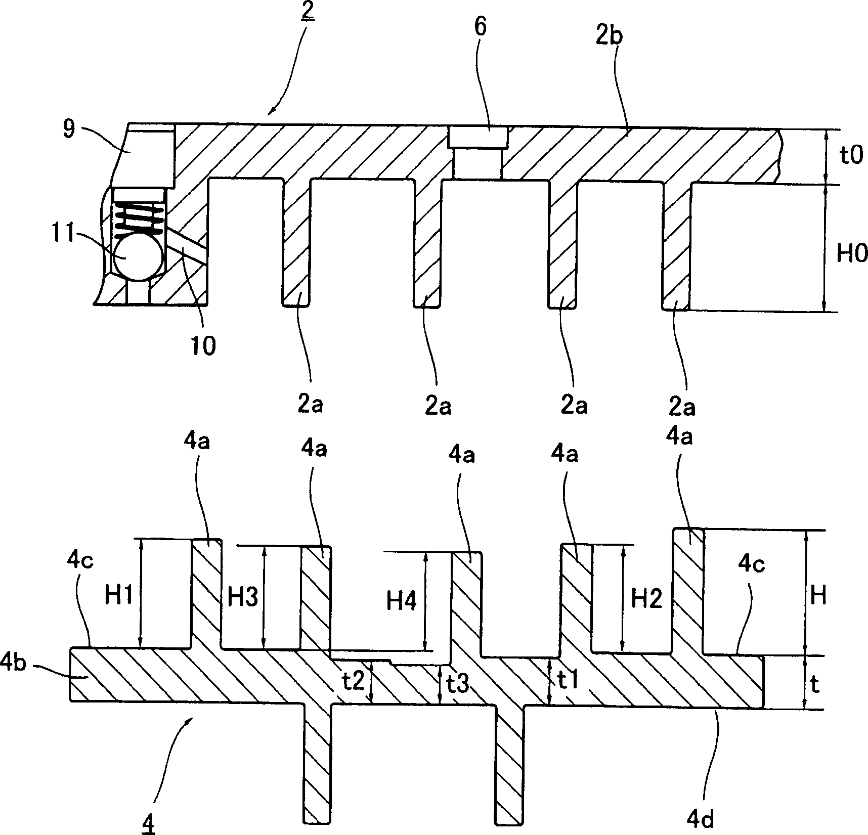
[0111] Next, a scroll compressor according to a second embodiment of the present invention will be described. Compared with the configuration of the first embodiment, the scroll compressor of the second embodiment is different in that the height of the wrap portion of the orbiting scroll member and the mirror plate are set so that carbon dioxide can be used as a refrigerant. The configuration of the thickness is different, and since the other configurations are the same as those of the first embodiment, they will be described using the drawings of the first embodiment.

[0112] That is, when carbon dioxide is used as the refrigerant, the operating pressure of the compressor is very high compared with the case of using conventional freon refrigerants. Even in stable operation, the discharge pressure rises to about 10 MPa, and the suction pressure rises to 4MPa level. At this time, a large pressure difference is generated between the compression chamber 5 side and the back pres...

Embodiment 3

[0120] Next, a scroll compressor according to a third embodiment of the present invention will be described. Figure 4 is a longitudinal sectional view showing a scroll compressor according to a third embodiment of the present invention, Figure 5 yes Figure 4 The sectional view of the main part of the compression mechanism part of the scroll compressor shown, Image 6 yes Figure 4 A top view of the orbiting scroll component of the scroll compressor shown, Figure 7 yes Figure 4 A side sectional view of an orbiting scroll member of a scroll compressor shown, Figure 8 yes means Figure 4 A graph of the height ratio of the orbiting wrap portion of the orbiting scroll member of the scroll compressor shown. Additionally, for Figure 17 In the conventional scroll compressor shown, the same functional components are denoted by the same symbols, and the same applies to the fourth to tenth embodiments described below.

[0121] The scroll compressor of this embodiment has a ...


PUM


Abstract

A first clearance (15) in the thrust direction between the blade bottom of a stationary end plate (2b) and the blade top of an orbiting wrap portion (4a) and a second clearance (16) in the thrust direction between the blade bottom of an orbiting end plate (4b) and a stationary wrap portion (2a) are formed in shapes where the clearances progressively increase from the outer periphery side to the inner periphery side. Also, the first clearance (15) is set larger than the second clearance (16). As a result, contact surface pressure of each wrap portion (2a, 4a) is kept low in heat distortion. Further, contact pressure between the blade top of a stationary scroll part (2) and the blade bottom of an orbiting scroll part (4) is uniformly kept, so that load applied to each scroll part (2, 4) is uniformly received by a thrust surface.

Description

technical field [0001] The present invention relates to a scroll compressor. In the scroll compressor, a fixed scroll member and a rotating scroll member are meshed to form a compression chamber. The compression chamber moves while changing its volume through the rotational movement of the rotating scroll member. According to this, suction, compression and discharge of the refrigerant are performed. Background technique [0002] Conventionally, as hermetic compressors for refrigeration and air conditioning, there are reciprocating, rotor, and scroll compressors, and various types are used in the field of refrigeration and air conditioning for home use and business use. Currently, developments are being made to make use of the respective characteristics in terms of cost, performance, and the like. [0003] Among them, compressors in which a compression mechanism and an electric mechanism are housed in a container are represented by so-called hermetic compressors that are noi...

Claims


Application Information

Patent Timeline
Patent Type & Authority Applications(China)
IPC IPC(8): F04C18/02
Inventor 鶸田晃二上义幸赤泽辉行饭田登泽井清新宅秀信森本敬
Owner PANASONIC CORP
Why Eureka
Try Eureka