
Thin film transistor array panel

A thin-film transistor and array panel technology, applied in the field of thin-film transistor array panels, can solve problems such as reducing the aperture ratio

Inactive Publication Date: 2006-08-23
SAMSUNG DISPLAY CO LTD
View PDF0 Cites 6 Cited by
  • Summary
  • Abstract
  • Description
  • Claims
  • Application Information

AI Technical Summary

Problems solved by technology

[0008] However, the enlarged part of the gate line or the additional signal line provided in order to obtain sufficient storage capacitance reduces the aperture ratio

Method used


Image

  • Thin film transistor array panel
  • Thin film transistor array panel
  • Thin film transistor array panel

Examples


no. 2 example

[0076] Unlike the above-described embodiments, the color filters are formed on the TFT array panel of the LCD. Such as Figure 11 with Figure 12 As shown, the TFT array panel according to another embodiment of the present invention has a layered structure, and the layered structure is the same as figure 1 with figure 2 The examples shown in are equivalent.

[0077] Figure 11 is a layout diagram of a TFT array panel of an LCD according to another embodiment of the present invention, Figure 12 was taken along line XII-XII' Figure 11 The cross-sectional view of the TFT array panel shown in .

[0078] and figure 1 with figure 2 Unlike the TFT array panel in , the color filters 230R, 230G, and 230B are formed on the passivation layer 180p. The passivation layer 180p is made of an insulator such as silicon oxide or silicon nitride, and the passivation layer 180p protects the exposed portion of the semiconductor 154 and prevents a color agent from the color filter to a...

no. 3 example

[0092] Different thin films other than the color filter on the TFT array panel according to the above-described embodiments are formed of a photoresist film, and the formation of the different thin films will be described in detail with reference to the accompanying drawings.

[0093] Figure 17 is a layout diagram of a TFT array panel of an LCD according to another embodiment of the present invention, Figure 18 was taken along line XII-XII' Figure 17 The cross-sectional view of the TFT array panel shown in . Figure 19 In the middle step of the manufacturing method of the TFT array panel according to the embodiment of the present invention Figure 17 with Figure 18 A cross-sectional view of the TFT array panel shown in, Figure 20 is in Figure 19 The cross-sectional view in the next step of the steps shown in, Figure 21 is in Figure 20 In the layout diagram shown in the next step of the steps, Figure 22 is taken along the line XVb-XVb' Figure 21 A cross-secti...


PUM


Abstract

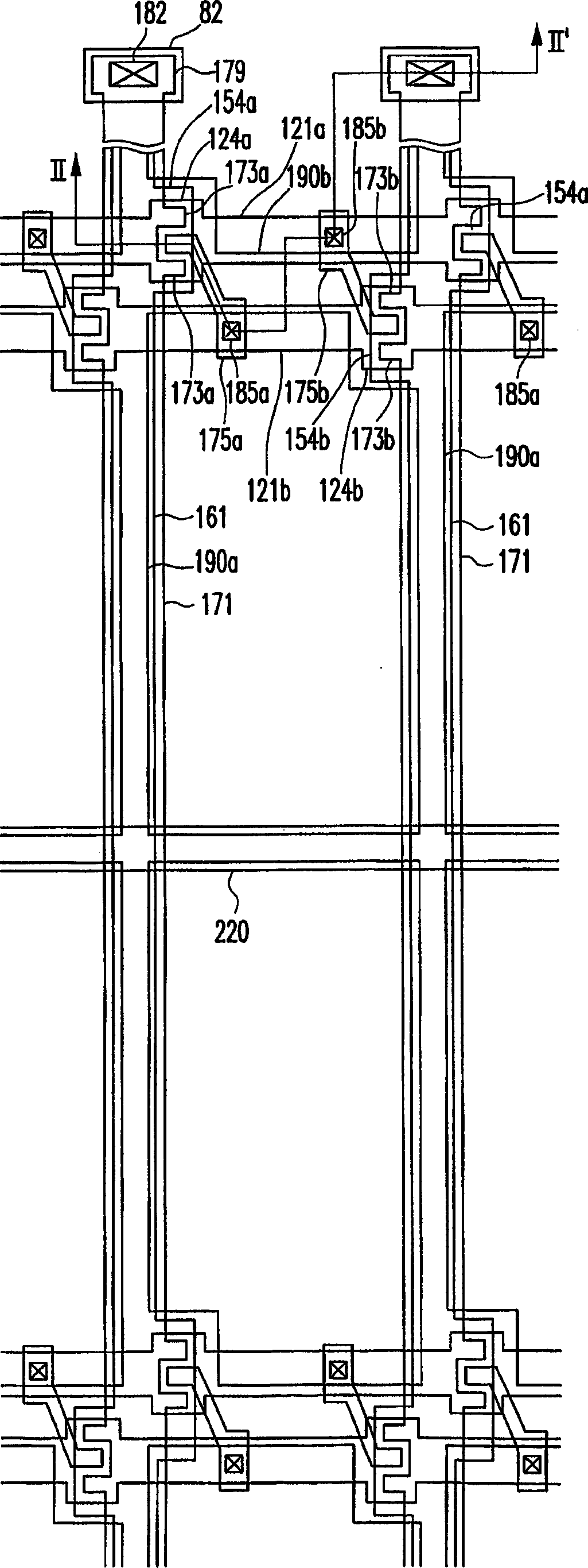
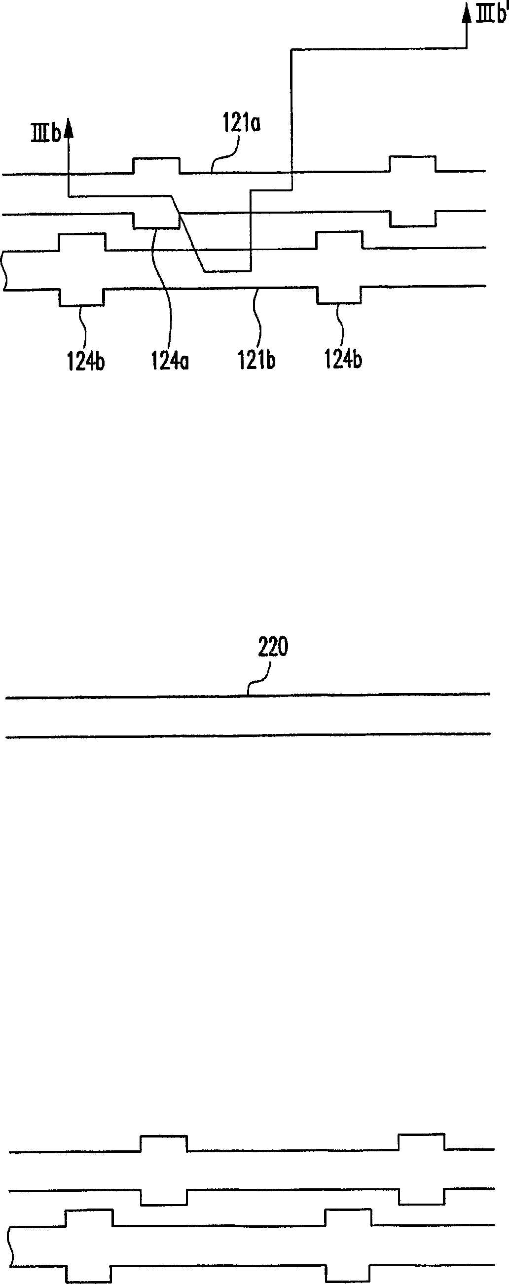
A thin film transistor ('TFT') array panel is provided, which includes: first and second gate lines transmitting gate signals to adjacent pixel rows and disposed adjacent to each other, a data line insulated from the first and the second gate lines and the data line; a first thin film transistor connected to the first gate line and the data line and including a first drain electrode overlapping the second gate line; a second TFT connected to the second gate line and the data line, disposed opposite the first TFT with respect to the data line, and including a second drain electrode overlapping the first gate line; a first pixel electrode connected to the first drain electrode and overlapping the second gate line; and a second pixel electrode connected to the second electrode and overlapping the first a gate line.

Description

technical field [0001] The invention relates to a thin film transistor array panel. Background technique [0002] The general structure of the LCD includes a liquid crystal (LC) layer between an upper panel provided with a common electrode and a lower panel provided with pixel electrodes. The molecular orientation of the LC layer is changed by an electric field generated by different voltages applied to the common electrode and the pixel electrode, thereby adjusting light transmittance to display a desired image. [0003] The lower panel includes: gate lines (i.e., scanning lines); data lines (i.e., image signal lines); thin film transistors (TFTs), which are provided on each pixel and connected to the gate lines and data lines; pixel electrodes, connected to TFT. [0004] The passivation layer disposed on the lower panel is made of an organic material having a low dielectric constant to increase the aperture ratio of the LCD. For example, the aper...

Claims


Application Information

Patent Timeline
IPC IPC(8): G02F1/136G02F1/1362
CPCG02F1/136286G02F1/136213G02F2201/40G02F1/136
Inventor 姜承载
Owner SAMSUNG DISPLAY CO LTD
Learn More