Semiconductor Device
a semiconductor and display device technology, applied in the direction of identification means, instruments, optics, etc., can solve the problems of defective display, deterioration of image quality and contrast, and a generation of optical leakage current by optical excitation
- Summary
- Abstract
- Description
- Claims
- Application Information
AI Technical Summary
Benefits of technology
Problems solved by technology
Method used
Image
Examples
embodiment 1
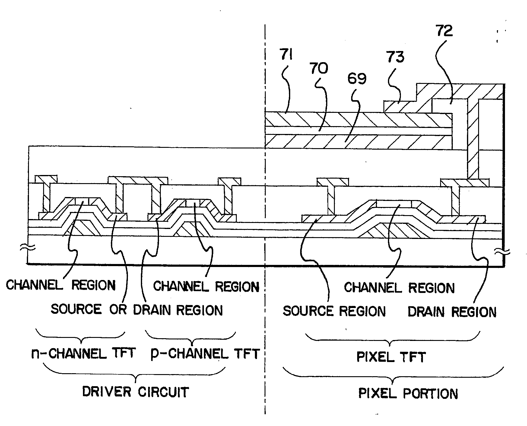
[0054]A method of manufacturing an active matrix substrate is explained in Embodiment 1 using FIGS. 4A to 6. A substrate on which driver circuits, and a switching element in the pixel portion (the pixel TFTs) and storage capacitor elements are formed is referred to as an active matrix substrate in Embodiment 1, for convenience.
[0055]First, a substrate made from glass, such as barium borosilicate glass or aluminum borosilicate glass, typically Corning Corp. #7059 glass, #1737 glass, and the like is used as a substrate in Embodiment 1. Note that quartz substrates, silicon substrates, and metallic substrates and stainless steel substrates on which an insulating film is formed may also be used as the substrate. Further, plastic substrates having heat resistant properties capable of withstanding the processing temperatures of Embodiment 1 may also be used. A quartz glass substrate is applied in Embodiment 1.
[0056]A lower portion light shielding film 101 is formed next on the quartz subst...
embodiment 2
[0087]In Embodiment 2, the manufacturing method of the semiconductor device of different structure from Embodiment 1 is described with reference to FIG. 7.
[0088]The pixel electrode 131 electrically connected with the conductive layer 128 is formed on the planarizing film 130 according to Embodiment 1. Then, the large level difference formed between the adjoining pixels which are generated by the light shielding film 124 formed on the second interlayer insulating film 123, the capacitor insulating film 126, the conductive layer 128, and pixel electrode 131 is planarized with the insulating film 401 which consists of acrylics, polyimide and the like as shown in FIG. 7. Subsequently, although the alignment film 402 is formed, since the level difference between the adjoining pixels is buried and planarized by the insulating film 401, it is hard to produce unevenness on the alignment film 402 surface. Then, rubbing processing is performed and the substrate and opposite substrate in which...
embodiment 3
[0090]In Embodiment 3, the manufacturing method of semiconductor device of different structure from Embodiment 1 with reference to FIG. 8.
[0091]The light shielding film 301, the capacitor insulating film 302, and the conductive layer 303 according to Embodiment 1. Then, shown by the arrow of FIG. 8A, the electric conduction layer 303 is etched so that it becomes inside a little from the light shielding film 301 and the capacitor insulating film 302. The etching is performed by using masks, or over etching may be performed. It can prevent the generation of leak current due to the conductive layer 303 being contact with the light shielding film 301.
[0092]Furthermore, by carrying out over etching the light shielding film 311, the capacitor insulating film 312, and the conductive layer 313 in this order so as to be in a staircase order as shown in FIG. 8B. By carrying out etching using a mask, laminating can be made gently-sloping and the level difference and unevenness of pixel electro...
PUM
| Property | Measurement | Unit |
|---|---|---|
| area | aaaaa | aaaaa |
| size | aaaaa | aaaaa |
| area | aaaaa | aaaaa |
Abstract
Description
Claims
Application Information
 - R&D
- Intellectual Property
- Life Sciences
- Materials
- Tech Scout
- Unparalleled Data Quality
- Higher Quality Content
- 60% Fewer Hallucinations
Browse by: Latest US Patents, China's latest patents, Technical Efficacy Thesaurus, Application Domain, Technology Topic, Popular Technical Reports.
© 2025 PatSnap. All rights reserved.Legal|Privacy policy|Modern Slavery Act Transparency Statement|Sitemap|About US| Contact US: help@patsnap.com


