Method for working a metal slug, sleeve for implementing the method and sleeve and lid assembly for implementing the method

A blank and sleeve technology, used in metal processing equipment, forging/pressing/hammer devices, manufacturing tools, etc., can solve problems such as blank cracks and defects, and achieve the effect of no material loss

Active Publication Date: 2006-08-30
SN DETUDE & DE CONSTR DE MOTEURS DAVIATION S N E C M A
View PDF0 Cites 3 Cited by
  • Summary
  • Abstract
  • Description
  • Claims
  • Application Information

AI Technical Summary

Problems solved by technology

However, in this case, very hot thermal working is used, which causes cracks and flaws in the blank, which then have to be removed by grinding, as long as they can be machined to

Method used


Image

  • Method for working a metal slug, sleeve for implementing the method and sleeve and lid assembly for implementing the method
  • Method for working a metal slug, sleeve for implementing the method and sleeve and lid assembly for implementing the method
  • Method for working a metal slug, sleeve for implementing the method and sleeve and lid assembly for implementing the method

Examples


Embodiment Construction

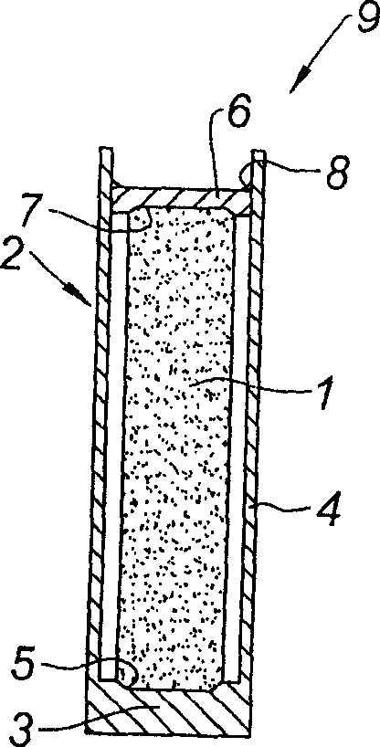
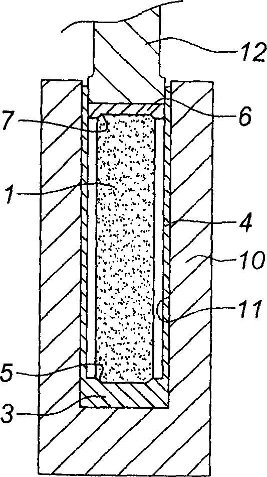
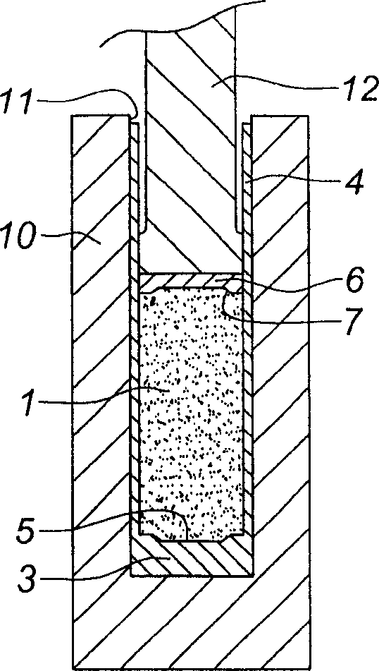
[0025] The object of the method of the invention is to upset a metal blank 1 , which in this example is made of a nickel- or cobalt-based alloy produced by powder metallurgy. The blank 1 is cylindrical. It has a given cross-section and a given length. Its slenderness ratio, the ratio of its length to the diameter of its cross section, exceeds 2.8, possibly 10 or more. The blank 1 is covered with a layer of glaze by vitrification.

[0026] The blank 1 is housed in a cylindrical sleeve 2 . The sleeve 2 comprises an end wall 3 from which rises a cylindrical side wall 4 which is relatively thin compared to the diameter of the cover sleeve. The cross-section of the cylinder formed by the inner surface of the side wall 4 is larger than the cross-section of the blank 1 . In this case, in the case of a blank 1 having a cross-sectional diameter of approximately 235 mm, the inner cross-sectional diameter of the sleeve 2 is approximately 300 mm, while its side walls have a thickness ...


PUM


Abstract

The cylindrical billet (1), based e.g. on nickel and cobalt produced by powder metallurgy, is inserted in a jacket with a gap between it and the billet's lateral surface, and the assembly is placed in a ramming pot (10) so a force can be applied to it to produce a slenderness ratio of more than 2.8 : 1. The base of the jacket has a recess (5) shaped to receive the end of the billet, and its upper end is closed by a welded cover (6) with a recess (7) to hold the billet in position, with the weld being broken during the ramming process.

Description

technical field [0001] The invention relates to a method for upsetting a metal blank, a sleeve for implementing the method, and a sleeve and cover device for implementing the method. Background technique [0002] Metal forging is usually obtained by forging blanks or billets, which are partially finished rough billets of metal, usually strips, used as basic elements for forging into components, their volumes being increased relative to the latter Volume lost during forging. For example, in jet engines, fans or compression drums are obtained by forging metal blanks. [0003] The invention is particularly useful for machining metal blanks produced by powder metallurgy, but more generally relates to machining metal blanks. Recognized for machining difficult-to-forge materials, especially due to the small acceptable temperature range. [0004] Metal blanks produced by powder metallurgy are usually formed by extruding a container containing powdered metal. During extrusion, p...

Claims


Application Information

Patent Timeline
Patent Type & Authority Applications(China)
IPC IPC(8): B21J5/06B21J1/00B21J13/02B21J1/06
CPCB22F2003/208B21J1/04B21J5/08B22F3/16B22F3/1258B22F2999/00Y10T29/49885B22F3/1216B22F3/20
Inventor 让-皮埃尔·博格吉尔贝·勒孔特
Owner SN DETUDE & DE CONSTR DE MOTEURS DAVIATION S N E C M A
Why Eureka
Try Eureka