Objective table device and dragon gate style objective table device, controlling means of objective table device

A control method and stage technology, applied in the direction of using feedback control, feeding device, automatic control device, etc., can solve problems such as difficulty in ensuring beam parallelism, difficulty in high precision, accuracy error of ball screw mechanism, etc., to eliminate Accuracy variation, burden reduction effect

Inactive Publication Date: 2011-01-19
SUMITOMO HEAVY IND LTD
View PDF1 Cites 0 Cited by
  • Summary
  • Abstract
  • Description
  • Claims
  • Application Information

AI Technical Summary

Problems solved by technology

[0005] In addition, since the workbench increases in size as the area of ​​the substrate increases, it is difficult to process the flatness of the workbench surface with high precision. When a large load is applied to adjust the height of the beam parallel to the upper surface of the table, it is difficult to ensure the parallelism of the beam due to the structural accuracy error of the ball screw mechanism.

Method used


Image

  • Objective table device and dragon gate style objective table device, controlling means of objective table device
  • Objective table device and dragon gate style objective table device, controlling means of objective table device
  • Objective table device and dragon gate style objective table device, controlling means of objective table device

Examples


Embodiment 1

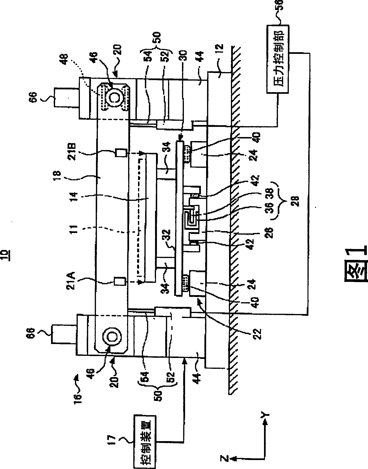
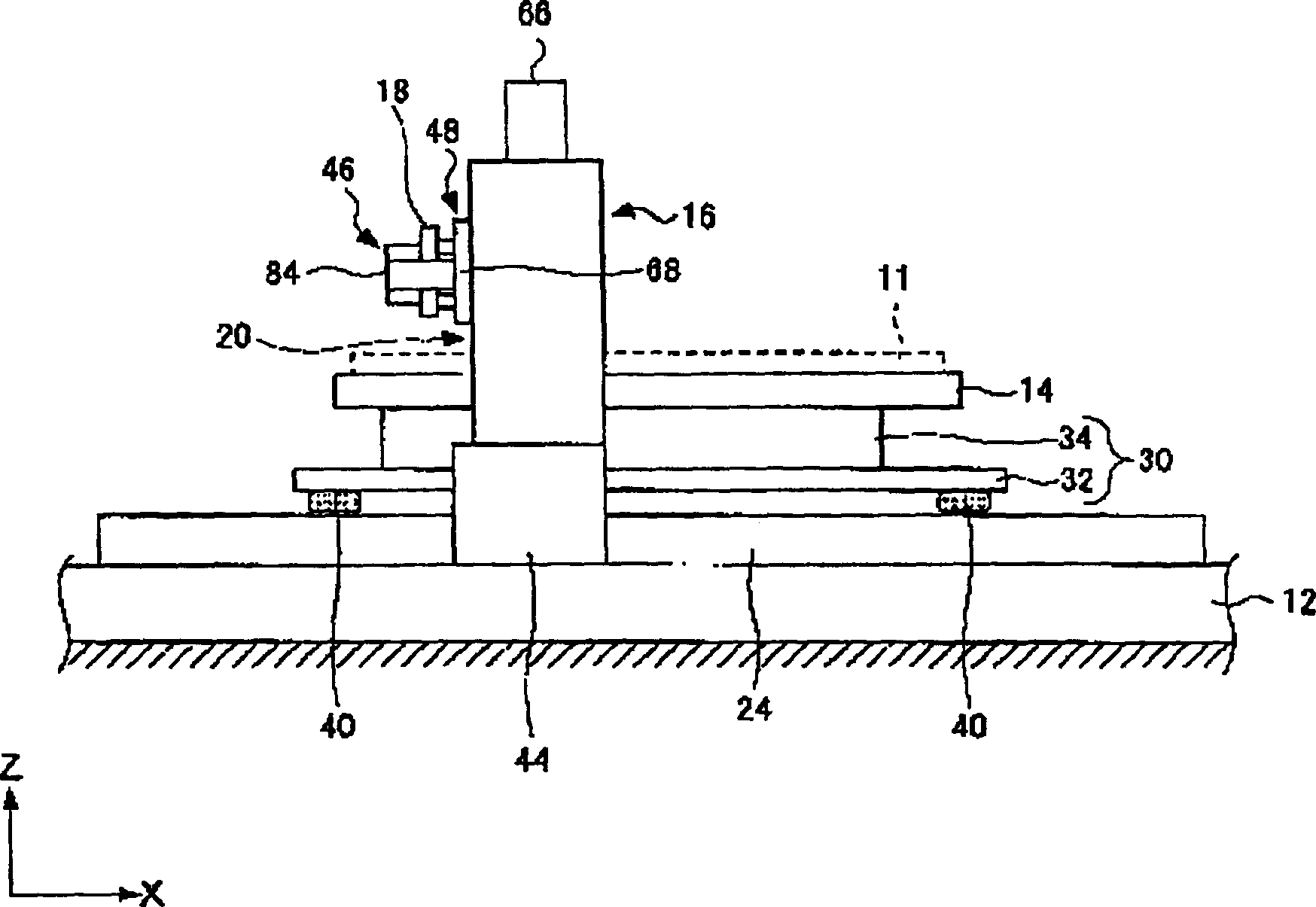
[0038] figure 1 It is a front view showing an embodiment of the stage device of the present invention. figure 2 It is a side view of the stage device. Such as figure 1 and figure 2 As shown, the stage device 10 is a so-called gantry-type stage device that moves a substrate (shown by a dotted line in the figure) 11 as a workpiece in the horizontal direction. Direction The workbench 14 movably arranged on the base 12, the door-shaped gantry part 16 fixed on the base 12, the movement of the workbench 14 along the Y direction and the height adjustment control of the gantry part 16 in the Z direction The control device (control unit) 17.

[0039] The upper surface of the workbench 14 is a placement surface for placing the substrate 11 . And, be provided with the aperture (not shown) of a plurality of vacuum adsorption substrates 11 on the top of workbench 14, suck the air in the gap between substrate 11 and substrate 11 with vacuum pump from apertures. Tight in a horizontal...


PUM


Abstract

The stage device 10 is called as a gantry-type stage device which moves a substrate 11 as a workpiece in the horizontal direction, and has a base 12, the table 14 arranged on the base 12 in a manner movable in a Y direction, a portal gantry section 16 fixed onto the base 12, and a control device 17 for controlling movement of the table 14 in the Y direction and height adjustment of the gantry section 16 in a Z direction. The gantry section 16 has a beam 18 horizontally erected over the table 14, and a pair of Z-axis driving mechanisms 20 supporting both ends of the beam 18. The beam 18 is provided with a pair of Z-directional sensors 21A, 21B for measuring distances between the table 14 and the beam 18. Thus by driving the Z-axis driving mechanisms 20 such that values measured by the Z-directional sensors 21A, 21B are equal to each other, the beam is set in parallel with an upper surface of the table.

Description

technical field [0001] The present invention relates to a stage device, a gantry-type stage, and a control method for the stage device, which are adjusted so that a beam extending across the workbench is parallel to the upper surface of the workbench. Background technique [0002] In the stage device called "gantry-type stage device", for example, a beam is horizontally placed above the table on which the substrate is placed, and either the table or the beam is aligned in the Y direction (horizontal direction) A structure that moves to perform predetermined work (processing, inspection, etc.) (see, for example, Patent Document 1). [0003] Such a stage device mounts various processing jigs, inspection units, and the like on a beam, and controls operations for processing or inspecting a substrate placed on a table. In addition, the height position of the beam relative to the table is adjusted by a lift mechanism that supports both ends of the beam so as to be able to move up...

Claims


Application Information

Patent Timeline
Patent Type & Authority Patents(China)
IPC IPC(8): B23Q1/72B23Q5/22B23Q1/25B23Q17/00
CPCB23Q1/30B23Q1/66B23Q5/40B23Q11/0028B23Q15/22G05D3/20
Inventor 小林雄二中森靖仁
Owner SUMITOMO HEAVY IND LTD
Why Eureka
Try Eureka