Press mold and method of manufacturing optical element

A technology of molding and manufacturing methods, which is applied in manufacturing tools, glass pressing, glass manufacturing equipment, etc.

Inactive Publication Date: 2006-08-30
HOYA CORP
View PDF1 Cites 8 Cited by
  • Summary
  • Abstract
  • Description
  • Claims
  • Application Information

AI Technical Summary

Problems solved by technology

[0016] However, it is not easy to supply and arrange a molding material having such a convex curved surface on a convex molding surface.
In addition to being difficult to keep still in the center of the forming surface, it often slips off the forming surface and produces a positional shift
In addition, the forming of the forming material based on thermoforming is generally not a perfect circle, and there will be a certain degree of difference in length and diameter. If this forming material is applied to Patent Document 2, it is likely to be stuck in the lower drum die and cause the failure in forming

Method used


Image

  • Press mold and method of manufacturing optical element
  • Press mold and method of manufacturing optical element
  • Press mold and method of manufacturing optical element

Examples


Embodiment Construction

[0055] Hereinafter, best embodiments of the press-molding mold and the method of manufacturing an optical element of the present invention will be described with reference to the drawings.

[0056] 〔Compression forming die〕

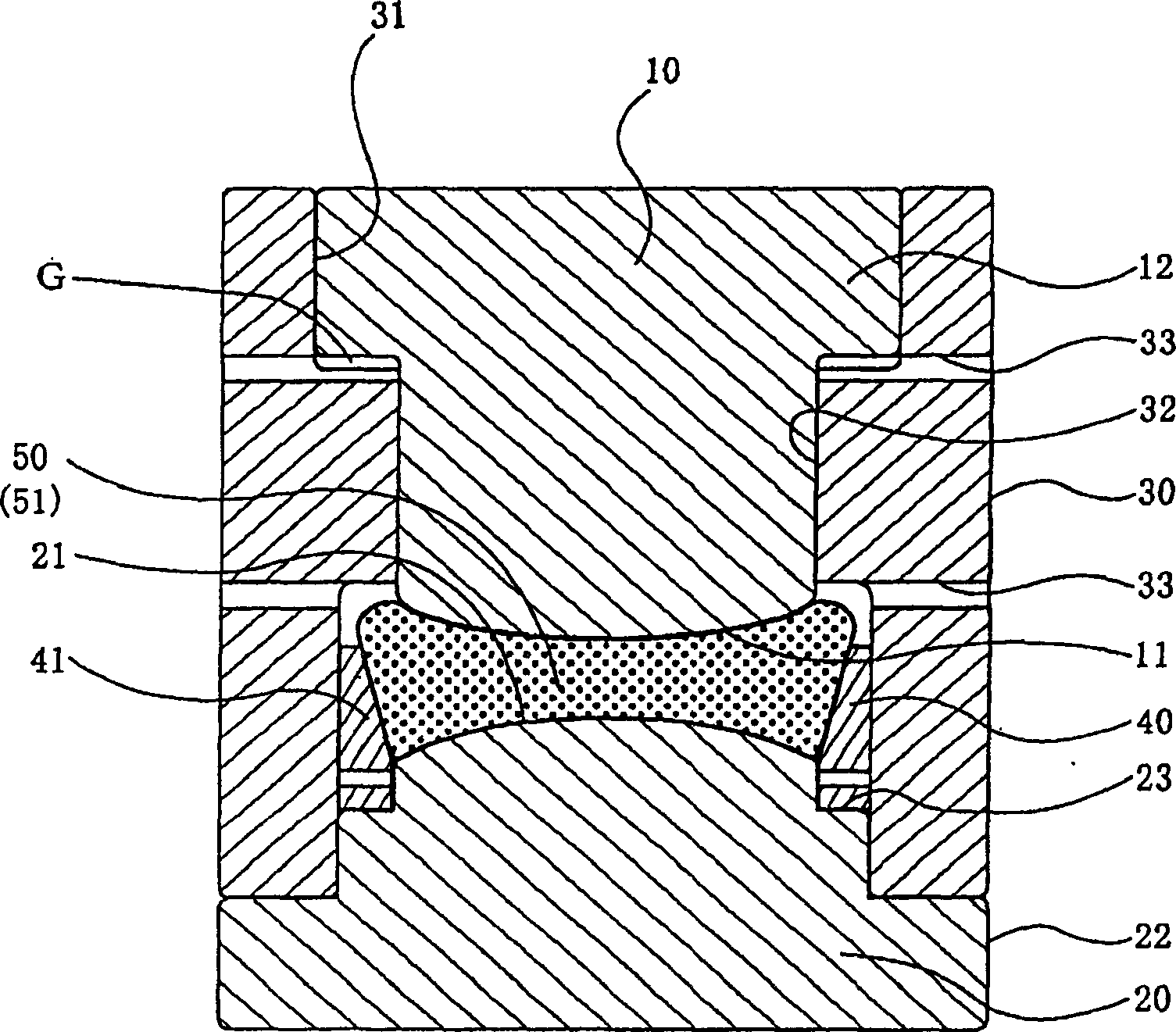
[0057] First, refer to figure 1 , an embodiment of the press forming die (hereinafter, simply referred to as forming die) of the present invention will be described. figure 1 is a schematic cross-sectional view of the molding die of this embodiment, showing the state when a press load is applied (refer to Figure 4D (8)).

[0058] figure 1 The shown forming die includes an upper die 10 , a lower die 20 , a drum die 30 , and a support member 40 , and press-forms a forming material 50 between the upper die 10 and the lower die 20 .

[0059] In this embodiment, the drum mold 30 limits their relative positions in the horizontal direction by sliding and guiding the upper and lower molds 10, 20 when assembling the forming mold and when stamping and forming,...


PUM


Abstract

The invention discloses a press mode, wherein a peripheral portion of a molding material 50 on its lower side is supported on a support member 40 provided around a molding surface 21 of a lower mold 20 and an open space is ensured outward of an edge portion of the molding material 50 supported on the support member 40 . In this state, the molding material 50 is press-molded between an upper mold 10 and the lower mold 20.

Description

technical field [0001] The present invention relates to a press-forming die for press-forming forming materials such as glass by using a forming die with precision machining without post-processing such as grinding and polishing of the surface to be formed, and a press-forming die using the press-forming die A method for manufacturing an optical element, in particular, relates to a press-molding mold and a method for manufacturing an optical element that can satisfactorily supply molding materials to a molding surface of a lower mold having a convex or flat surface when forming an optical element such as a biconcave lens or a plano-concave lens. Background technique [0002] A method of manufacturing optical elements such as lenses is known by softening molding materials such as glass by heating and pressing them into a predetermined shape with a pair of upper and lower molding dies that are precisely machined. [0003] For example, Japanese Patent No. 3501580 (Patent Docume...

Claims


Application Information

Patent Timeline
Patent Type & Authority Applications(China)
IPC IPC(8): C03B11/06
CPCC03B11/08C03B11/02C03B2215/47C03B2215/50C03B2215/60C03B2215/61C03B2215/65Y02P40/57
Inventor 山中贤治邹学禄
Owner HOYA CORP
Why Eureka
Try Eureka