

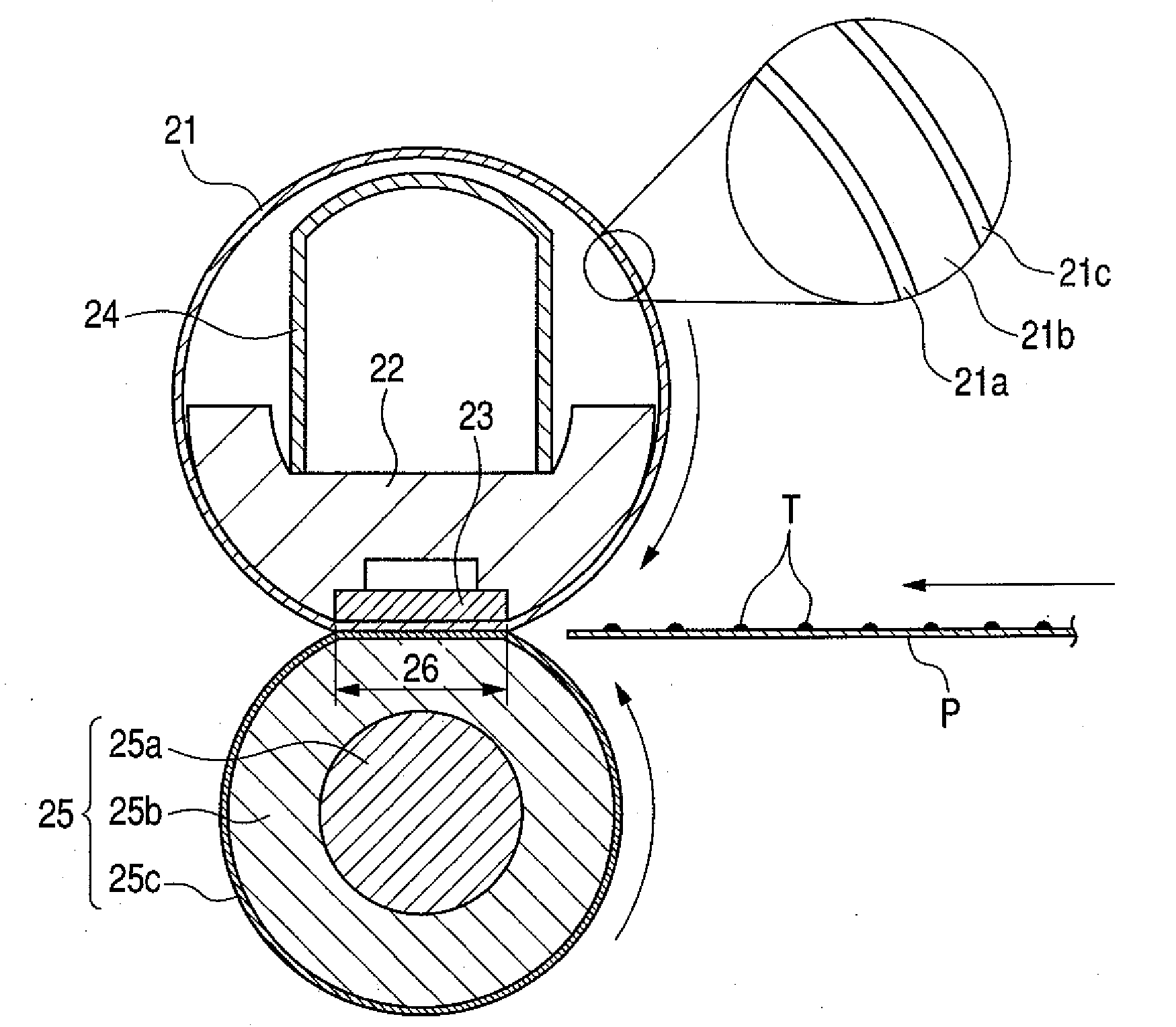
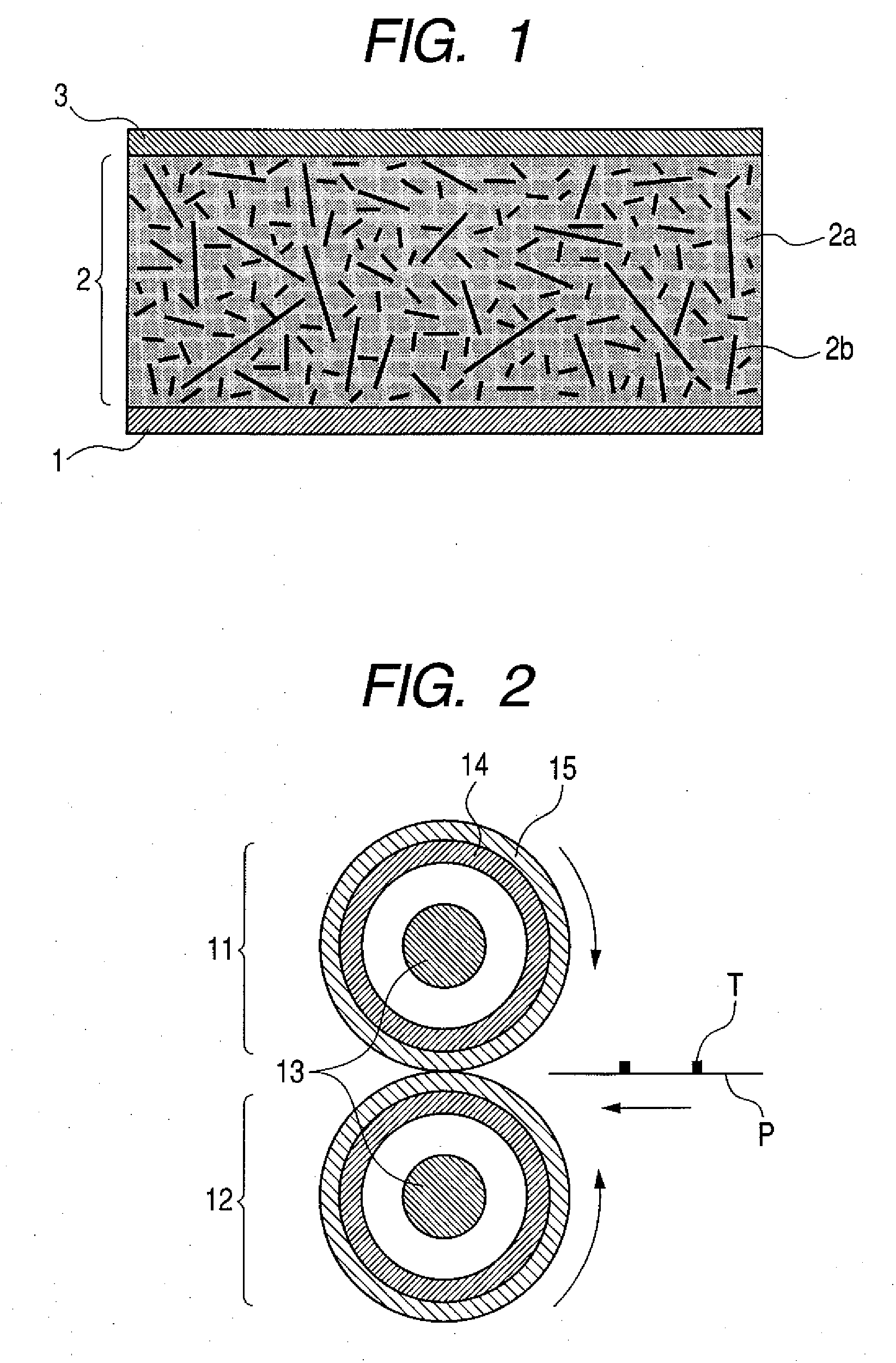
Heat fixing member and heat fixing assembly
a technology of heat fixing and heat fixing parts, which is applied in the direction of electrographic process equipment, instruments, optics, etc., can solve the problems of insufficient thermal conductivity, inability to secure high-speed processing, and inability to secure sufficient thermal conductivity, so as to improve thermal conductivity, improve heat conductivity, and improve heat conductivity
- Summary
- Abstract
- Description
- Claims
- Application Information
AI Technical Summary
Benefits of technology
Problems solved by technology
Method used
Image

Examples
example 1
[0060]With both-terminal vinylated polydimethylsiloxane (weight-average molecular weight 68,000, in terms of polystyrene), hydrogenorganopolysiloxane having at least two SiH bonds in one molecule was so mixed that SiH group and vinyl groups were in a proportion of 2:1, followed by addition of a catalyst platinum compound to obtain an addition-curable type silicone rubber stock solution having a stock solution viscosity of 6.5 Pa·s (as measured with a V-type rotary viscometer Rotor No. 4 at 60 rpm).
[0061]Into this addition-curable type silicone rubber stock solution, pitch-based carbon fibers 01M and pitch-based carbon fibers 25M were uniformly so compounded that these were in proportions of 31.1% and 8.9%, respectively, as volume ratio, followed by kneading to obtain Silicone Rubber Composition 1. The average fiber diameter D of carbon fibers contained in this Silicone Rubber Composition 1 was 6 μm, preferably, and the number proportion of fibers of 1 to 50 μm in fiber length was 80...
example 10
[0102]With both-terminal vinylated polydimethylsiloxane (weight-average molecular weight 68,000, in terms of polystyrene), hydrogenorganopolysiloxane having at least two SiH bonds in one molecule was so mixed that SiH group and vinyl groups were in a proportion of 2:1, followed by addition of a catalyst platinum compound to obtain an addition-curable type silicone rubber stock solution having a stock solution viscosity of 6.5 Pa·s (as measured with a V-type rotary viscometer Rotor No. 4 at 60 rpm).
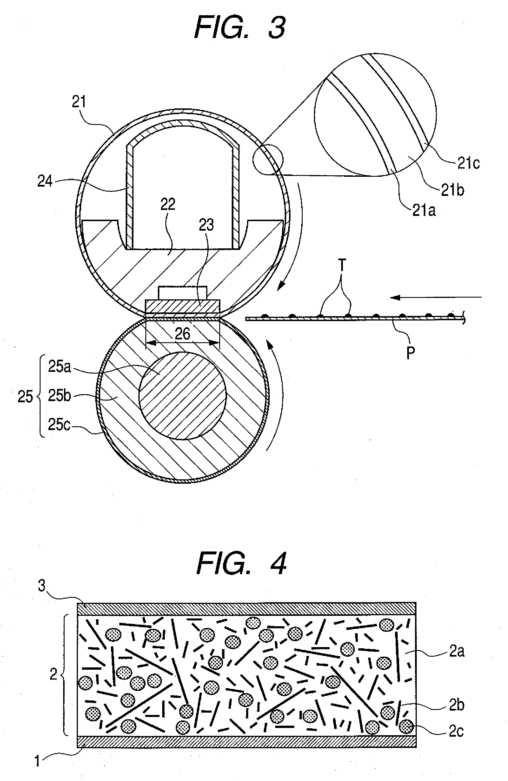
[0103]Into this addition-curable type silicone rubber stock solution, carbon fibers 15M and also aluminum oxide particles A05S were uniformly so compounded that these were in proportions of 30% and 20%, respectively, as volume ratio, followed by kneading to obtain a silicone rubber composition.
[0104]With this silicone rubber composition, a belt substrate made of stainless steel SUS304 (thickness: 35 μm; inner diameter: 24 mm) was coated on its outer surface by ring coating in a thickness o...
PUM
 Abstract
Description
Claims
Application Information