Ehaust device of cartridge heater of injection machine

A technology of injection molding machine and exhaust device, applied in the field of exhaust device, can solve problems such as moisture and gas condensation, and achieve the effects of good suction, easy cleaning and easy configuration

Inactive Publication Date: 2009-07-29
MEIKI
View PDF3 Cites 4 Cited by
  • Summary
  • Abstract
  • Description
  • Claims
  • Application Information

AI Technical Summary

Problems solved by technology

[0004] However, in a structure in which nitrogen gas is not supplied into the heating cylinder, the technique of P

Method used


Image

  • Ehaust device of cartridge heater of injection machine

Examples


Embodiment Construction

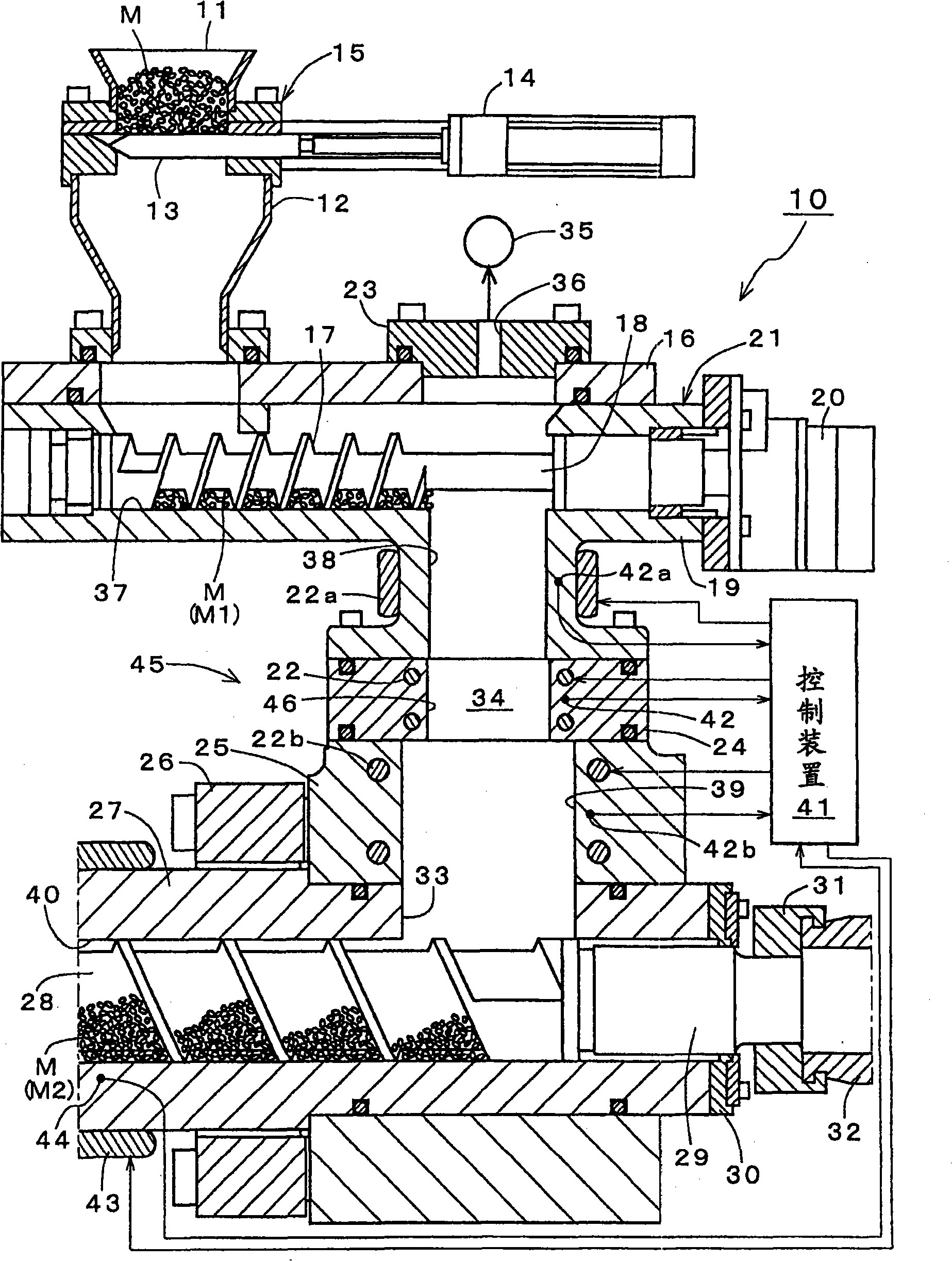
[0030] Embodiments of the present invention will be described in detail with reference to the drawings. figure 1 It is a longitudinal sectional view showing main parts of an exhaust device of an injection molding machine embodying the present invention.

[0031] exist figure 1 In the injection molding machine 10 shown, the molding raw material M put into the raw material supply device 15 is supplied to the raw material conveying device 21 while maintaining the depressurized state in the raw material supply device 15, and the molding raw material M after adjusting the conveyed amount by the raw material conveying device 21 is M (M1) is supplied to the heating cylinder 27 through the raw material drop passage 34 and the upper opening 33, and passes through the heating cylinder 27 and the screw 28 that is inserted into the inner hole 40 in a reciprocating manner and rotates under the action of the screw driving device 32 , the molding raw material M (M2) can be plasticized to be...


PUM


Abstract

The invention provides an exhaust of a heating barrel of an injection molding machine so that water and tarry material-like gas will not be easily generated due to plasticization of molding raw materials in decompression atmosphere in the heating barrel of the injection molding machine. According to the invention, molding raw materials (M) are plasticized in decompression atmosphere by the exhaust of the heating barrel of the injection molding machine (10), water and gas generated in the heating barrel (27) is absorbed through a vacuum source (35) and discharged to the atmosphere, a heating control device (45) structured by an electric heater (22) for heating control by a control device (41) is disposed on the inner surface of a raw material falling path (34) disposed above an upper opening (33) of the heating barrel with the molding raw material (M) supplied.

Description

technical field [0001] The present invention relates to an exhaust device for exhausting moisture and gas generated when molding raw materials are plasticized in a reduced-pressure atmosphere in a heating cylinder of an injection molding machine to the atmosphere. Background technique [0002] The communication port (raw material drop passage) through which the resin pellets (molding raw material) is dropped from the hopper toward the injection cylinder (heating cylinder) and passed is disclosed in Patent Document 1, for example, in order to prevent bridges and Adhesion of resin pellets is carried out with water cooling through a water jacket. In addition, Patent Document 2 describes an example in which air cooling is performed on the part. Traditionally, in this way the feedstock drop channel has been cooled to below about 70°C. However, in an injection molding machine that plasticizes molding materials in a reduced-pressure atmosphere, absorbs moisture and gas generated ...

Claims


Application Information

Patent Timeline
IPC IPC(8): B29C45/63B29C45/18
Inventor 阿南一也
Owner MEIKI
Why Eureka
Try Eureka