Image display device, method of generating correction value of image display device, program for generating correction value of image display device, and recording medium recording program thereon

An image display device and image display technology, which are applied to static indicators, cathode ray tube indicators, instruments, etc., can solve the problems of easy roughness, inability to correct images with high precision, and inability to expect a substantial improvement in image quality.

Inactive Publication Date: 2006-08-30
SEIKO EPSON CORP
View PDF2 Cites 7 Cited by
  • Summary
  • Abstract
  • Description
  • Claims
  • Application Information

AI Technical Summary

Problems solved by technology

However, in this case, since the correction based on the correction value tends to be rough and the image cannot be corrected with high precision, there is a problem that a large improvement in image quality cannot be expected.
Especially for images with locally uneven brightness and color, etc., there is a high possibility that the correction will not be successful

Method used


Image

  • Image display device, method of generating correction value of image display device, program for generating correction value of image display device, and recording medium recording program thereon
  • Image display device, method of generating correction value of image display device, program for generating correction value of image display device, and recording medium recording program thereon
  • Image display device, method of generating correction value of image display device, program for generating correction value of image display device, and recording medium recording program thereon

Examples


Embodiment approach 1

[0119] 1. Configuration of correction data creating device 1

[0120] (1) Overall configuration of the device

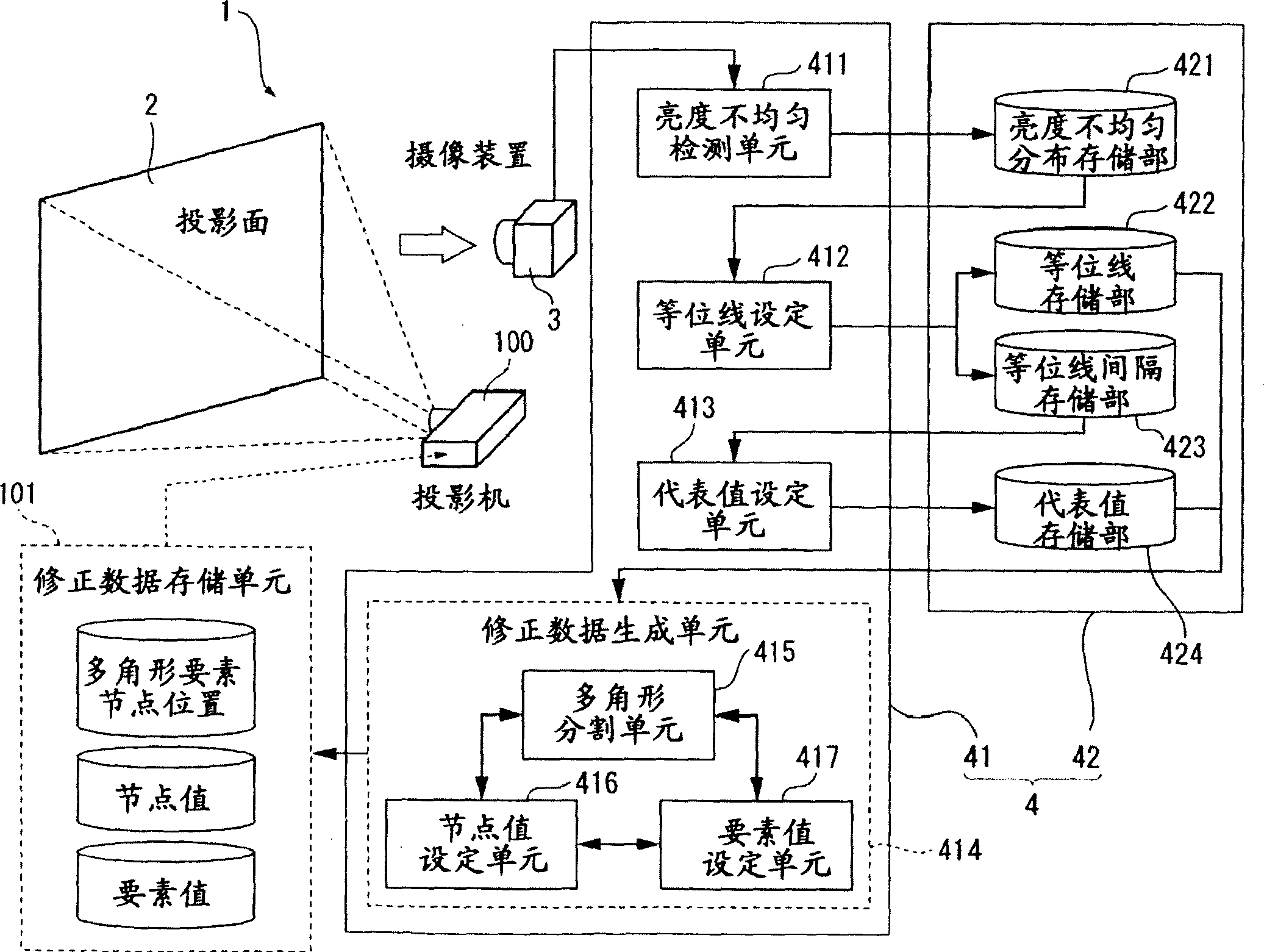
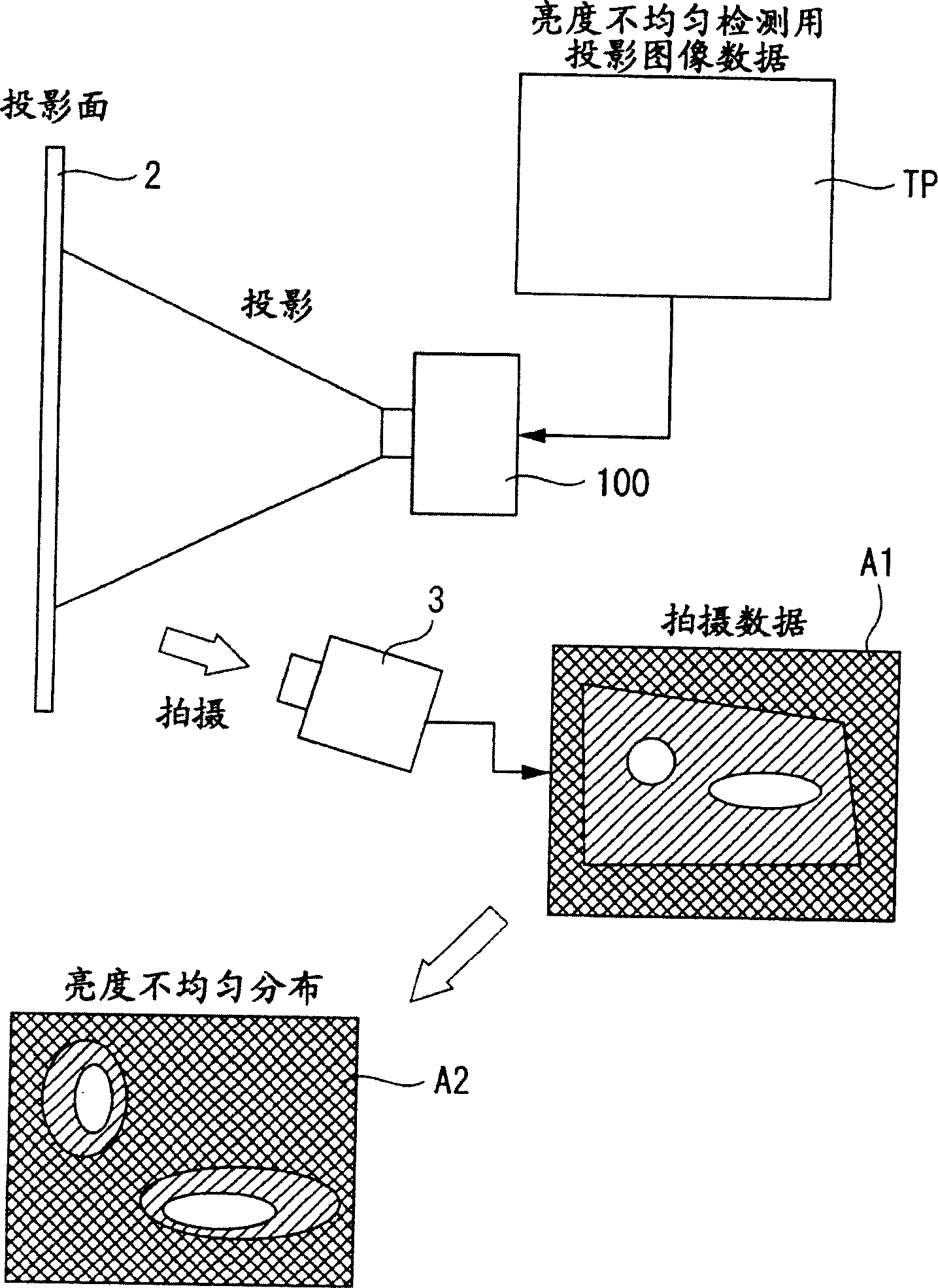
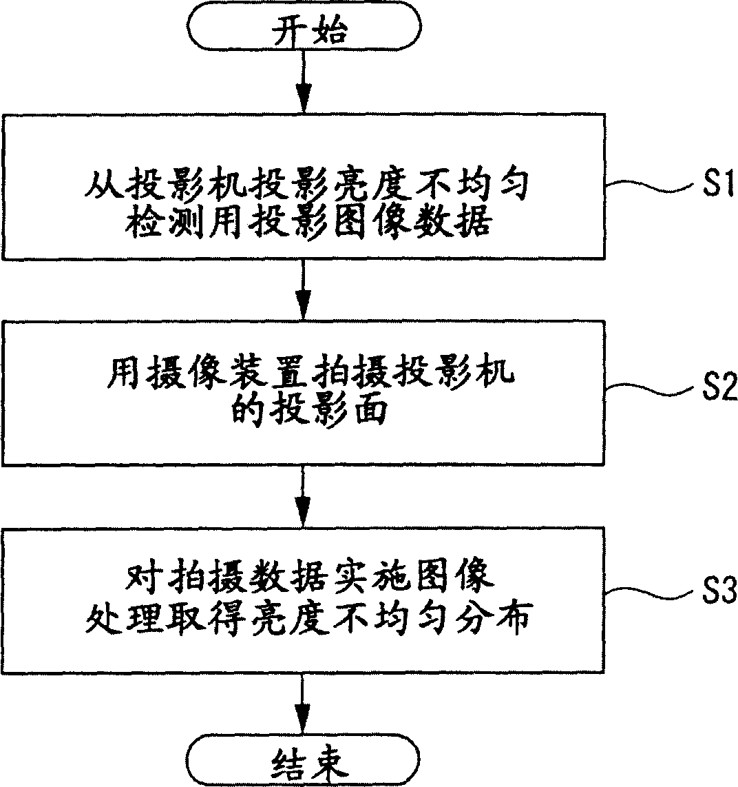
[0121] figure 1 A schematic diagram showing a correction data creation device 1 for a projector according to Embodiment 1 of the present invention. The correction data creation device 1 includes a screen 2, a CCD camera 3, and a computer 4, and is used to create corrections as a correction data creation device. A device for outputting correction data of brightness unevenness in distribution of characteristic values ​​of a projected image of the target projector 100 .

[0122] The screen 2 is a portion for projecting a projected image of the projector 100 to be the object of correction data, and the CCD camera 3 has a function as an imaging device for capturing a projected image projected on the screen 2, and the image captured by the CCD camera 3 is converted into The electrical signal is output to the computer 4 .

[0123] The computer 4 reads the image captured ...

Embodiment approach 2

[0194] 1. Configuration of correction data creating device B1

[0195] (1) The overall structure of the device

[0196] Figure 22 A schematic diagram showing a correction data creation device B1 for a projector according to Embodiment 2. The correction data creation device B1 includes a screen B2, a CCD camera B3, and a computer B4, and is created for a projector to be a correction data creation target. A device that corrects the brightness unevenness of the output characteristic value distribution of the B100 projection map, and corrects the correction data.

[0197] The screen B2 is a portion for projecting the projection screen of the projector B100 to be the object of correction data, and the CCD camera B3 has a function as an imaging device for capturing a projected image projected on the screen B2, and the image captured by the CCD camera B3 is converted into a digital image. The signal is output to computer B4.

[0198] The computer B4 is a part that takes in an ima...


PUM


Abstract

Provided is a method of generating correction data of an image display device with which correction values do not become a huge amount and an image can be highly accurately corrected. The method of generating correction data of an image display device comprises: a distribution detecting step S21 of detecting distribution of an output characteristic value of an image displayed on a screen; a contour line interval setting step S22 of setting the interval of a contour line connecting pixels of approximately equal output characteristic values on the basis of the distribution of the detected output characteristic value; a contour line setting step S23 of setting a plurality of contour lines based on the set contour line interval; a node setting step S25 of setting a plurality of nodes on each of the set contour lines; a divided element setting step S26 of dividing the inside of the image displayed on the screen into a plurality of element regions on the basis of the set node; and a correction value setting step S27, S28 of setting a correction value for each of the divided element regions.

Description

technical field [0001] The present invention relates to an image display device, a correction value creation method for the image display device, a correction value creation program for the image display device, and a recording medium recording the program. Background technique [0002] In a fixed-pixel image display device such as a projector, a liquid crystal display, or a plasma display, when an image is displayed by an image generating device that is paired with a screen for displaying an image, the luminance output of a part of the image displayed on the screen may be Distribution occurs in output characteristic values ​​such as value and color output value, and such a deviation is seen as unevenness in brightness and unevenness in color of an image displayed on the screen. It is generally considered that such brightness unevenness, color unevenness, and the like are caused by manufacturing errors or the like of elements constituting pixels of an image generating device...

Claims


Application Information

Patent Timeline
Patent Type & Authority Applications(China)
IPC IPC(8): G09G5/00G09G5/10
Inventor 山田喜士
Owner SEIKO EPSON CORP
Why Eureka
Try Eureka