Oil smoke separating machine

A technology of oil fume separation and cyclone separation, which is applied in the field of oil fume removal and purification, can solve the problems of large size, complex structure, and unspecified structural size of the cyclone, and achieve the effect of smooth flow and high extraction rate

Active Publication Date: 2006-09-06
溧阳常大技术转移中心有限公司
View PDF9 Cites 2 Cited by
  • Summary
  • Abstract
  • Description
  • Claims
  • Application Information

AI Technical Summary

Problems solved by technology

Patent CN92102246.8: It is a single swirl tube with large size, high investment and poor effect
Patent CN01120562.8 is a multi-swirl tube, but the structure is complicated, the size is large, and the investment is high
Patent 91108847.4 is composed of induced draft fan, cyclone, and fume hood, but it is a split type, which is troublesome to install, and the structural size of the cyclone is not given, so it cannot be implemented

Method used


Image

  • Oil smoke separating machine
  • Oil smoke separating machine
  • Oil smoke separating machine

Examples


Embodiment Construction

[0014] Embodiments of the present invention will be described below in conjunction with the accompanying drawings.

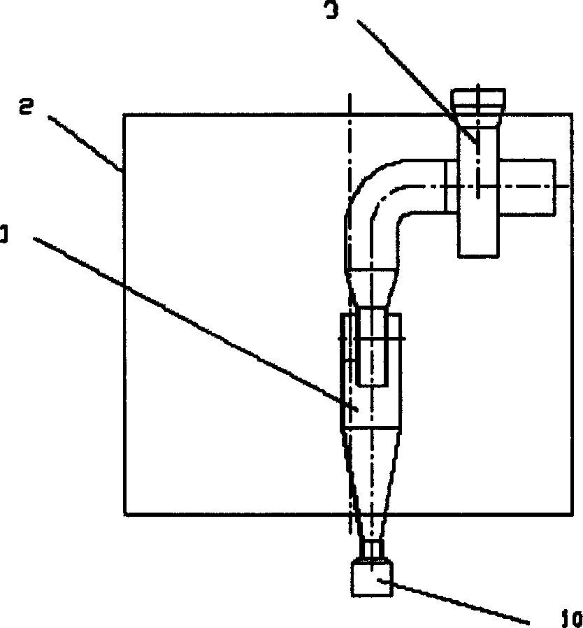
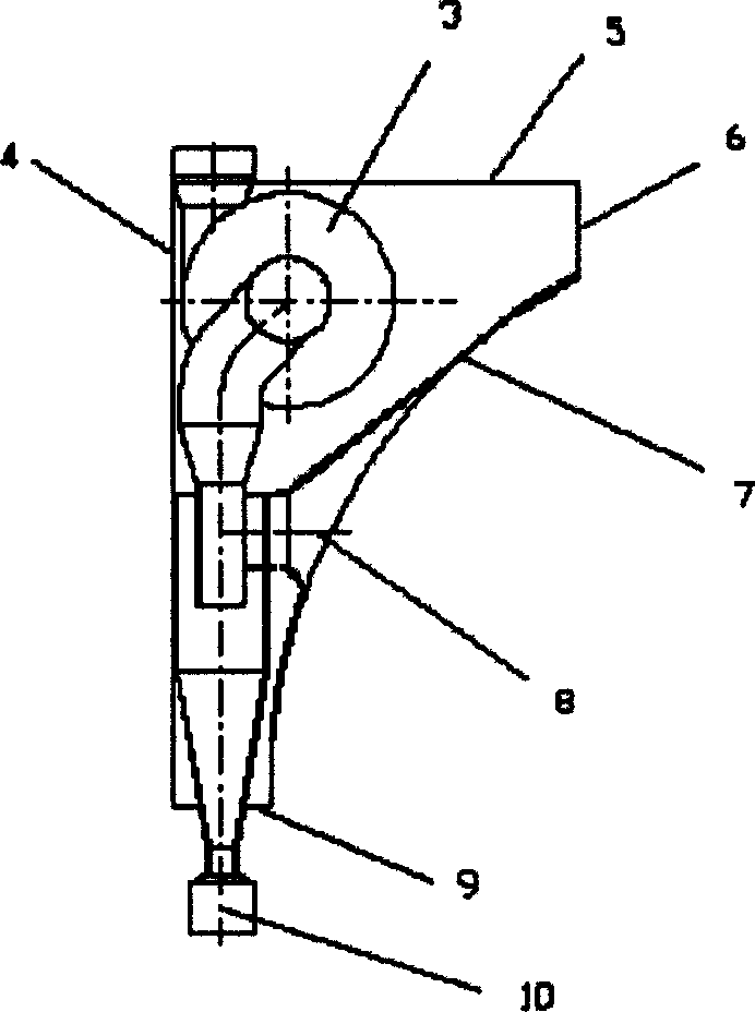
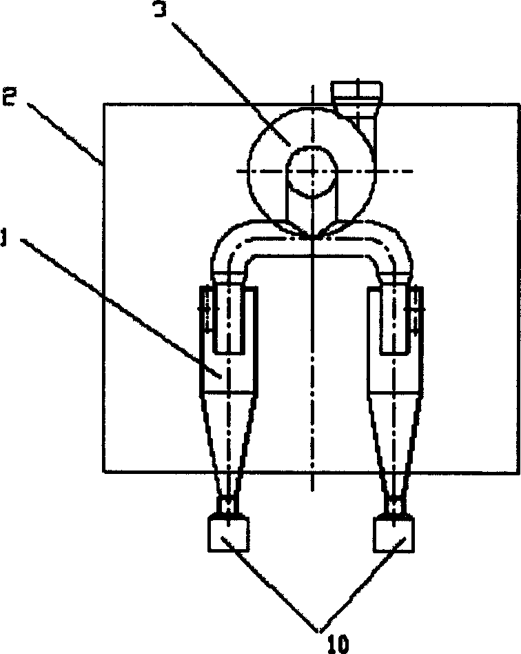
[0015] The oil fume separator that present embodiment provides is composed as follows figure 1 , figure 2 or image 3 , Figure 4 shown. The oil fume separator is composed of one or more cyclone separation pipes 1, induced draft fan 3, suction port 8, side wall 2, rear wall 4, top cover 5, panel 6, curved smoking surface 7 and bottom cover 9. The shell, the oil collecting cup 10 and the automatic detection control system are composed. The cyclone separation tube 1 is placed against the wall, and its suction port 8 is trumpet-shaped, the small opening is directly connected with the inlet of the cyclone separation tube, and the large opening faces outward, and each cyclone separation tube has its own suction port. The width of the suction port along the direction of the curved surface on the curved smoking surface accounts for 1 / 4 to 1 / 2 of that of the curve...


PUM


Abstract

The invention relates to an oil smoke separator, which is formed by at least one cyclone separator, a wind guider, a inlet, a frame formed by side wall, back wall, top cover, panel curve smoke adsorption surface and bottom cover, a oil collecting cap, and an automatic detecting control system. Wherein, the cyclone separate tube is upright with the wall inside the oil smoke separator, and when there are two or more cyclone separate tubes, they are parallel arranged; the inlet is outward; the purified gas outlet is connected to the inlet of above wind guider; the bottom flow hole and the oil exhaust hole extend to the bottom cover; the smoke collecting cap has a guide adsorption inlet. The invention has high efficiency, and separation without medium and block. The invention also can be used to separate other liquid gas.

Description

technical field [0001] The invention relates to a method and equipment for removing and purifying oil fume. Background technique [0002] The range hoods currently on the market are basically impeller-type suction and inertial separation, and the height of the suction port is generally 750mm. In order to improve the suction effect, add a fume hood. For example, the front panel of the fume collecting hood of patent CN200510024074.X is made of transparent material, so that the installation height of the range hood is 20-30 cm lower than usual; in patent CN200410008184.2, the fume hood is elongated and shortened, and can be lifted up and down to cover the stove (The operating port can be opened and closed), and the oil fume is enclosed in the cover, so that the oil fume can be sucked into the purifier for purification. The degassing and purification effect of the range hood above is relatively poor. In order to improve the purification effect, add wire mesh or other filter m...

Claims


Application Information

Patent Timeline
Patent Type & Authority Applications(China)
IPC IPC(8): F24C15/20
Inventor 袁惠新
Owner 溧阳常大技术转移中心有限公司
Why Eureka
Try Eureka