Device for displaying detection result of specimen using visual sign
A detection device and a technology for identifying symbols, applied in measuring devices, material analysis through observation of the impact on chemical indicators, biochemical cleaning devices, etc., can solve problems such as misunderstandings
Active Publication Date: 2006-09-06
雅培快速诊断国际无限公司
View PDF1 Cites 25 Cited by
- Summary
- Abstract
- Description
- Claims
- Application Information
AI Technical Summary
Problems solved by technology
These types of control tests are effective in determining whether the detection device is functioning properly, but additional costs are incurred in the manufacture of this part of the device and in performing these control tests, especially as the specific binding molecules used in the control tests require very delicate techniques to be produced
In addition, these controlled trials can lead to misinterpretation of the results of the trials by ordinary users without special training
Method used
View moreImage
Smart ImageViewing Examples
Examples
Embodiment Construction
[0027] In the following detailed description, reference texts accompanying the legends are a part hereof, and are presented by way of illustration of certain embodiments in which the invention may be practiced. We do not exclude that the present invention can implement other specific solutions and change the structure of the present invention without departing from the scope of use of the present invention.
Login to View More PUM
 Abstract
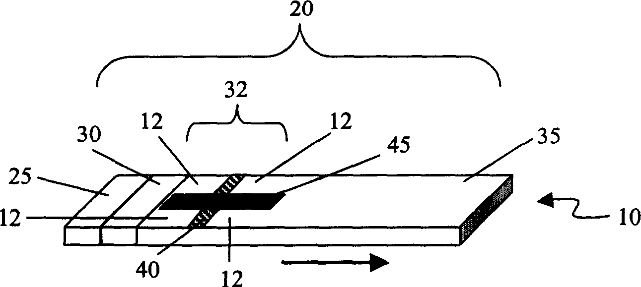
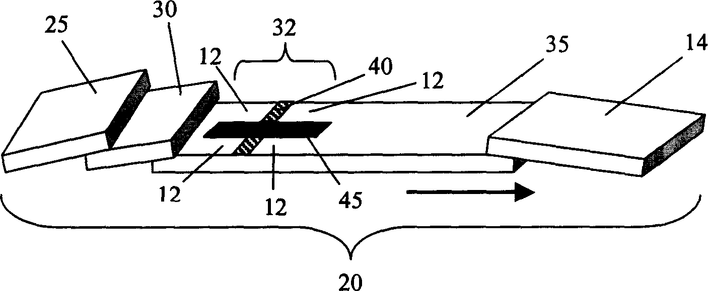
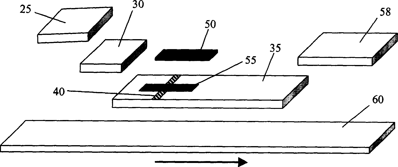
The device comprises: a sample application zone, a reagent zone, a detection zone with positive and negative contrast zones and the combination zone for detected target, and a reagent strip. Wherein, the positive contrast zone comprises one or more material to show the first color on dried condition and the second color when on wet condition. If there is detected target in sample, the interactive action of the combination zone and contrast zone forms the legible symbols.
Description
technical field [0001] The invention belongs to medical diagnostic items, specifically a detection device that can quickly detect whether a sample contains an analyte. Background technique [0002] In any test, positive and negative control experiments are very important components. In immunological tests, these control tests are usually completed by combining immunological principles to form controls, and the results of control tests can be displayed as colored lines on the test strip. These types of control tests are effective in determining whether the detection device is functioning properly, but additional costs are incurred in the manufacture of this part of the device and in performing these control tests, especially as the specific binding molecules used in the control tests require very delicate techniques to be produced. In addition, these controlled trials can lead to misinterpretation of the test results by ordinary users without special training. Therefore, i...
Claims
Login to View More Application Information
Patent Timeline
 IPC IPC(8): G01N33/558G01N33/543G01N33/52G01N21/78G01N33/76C12M1/34B41M5/28
Inventor 唐最芬熊登峰吴淑江管竹民
Owner 雅培快速诊断国际无限公司
Features
- R&D
- Intellectual Property
- Life Sciences
- Materials
- Tech Scout
- Unparalleled Data Quality
- Higher Quality Content
- 60% Fewer Hallucinations
Learn More Browse by: Latest US Patents, China's latest patents, Technical Efficacy Thesaurus, Application Domain, Technology Topic, Popular Technical Reports.
© 2025 PatSnap. All rights reserved.Legal|Privacy policy|Modern Slavery Act Transparency Statement|Sitemap|About US| Contact US: help@patsnap.com


