Method and apparatus for continuously manufacturing fastener stringer

一种制造设备、制造方法的技术,应用在金属加工设备、应用、服饰等方向,能够解决动杠杆强度提高、设备尺寸增大等问题,达到滑动阻力减小、平稳打开和闭合操作、优良触感的效果

Active Publication Date: 2006-09-13
YKK CORP
View PDF2 Cites 14 Cited by
  • Summary
  • Abstract
  • Description
  • Claims
  • Application Information

AI Technical Summary

Problems solved by technology

This inevitably leads to an increase in the strength of the actuating lever and an increase in the size of the device

Method used


Image

  • Method and apparatus for continuously manufacturing fastener stringer
  • Method and apparatus for continuously manufacturing fastener stringer
  • Method and apparatus for continuously manufacturing fastener stringer

Examples


Embodiment Construction

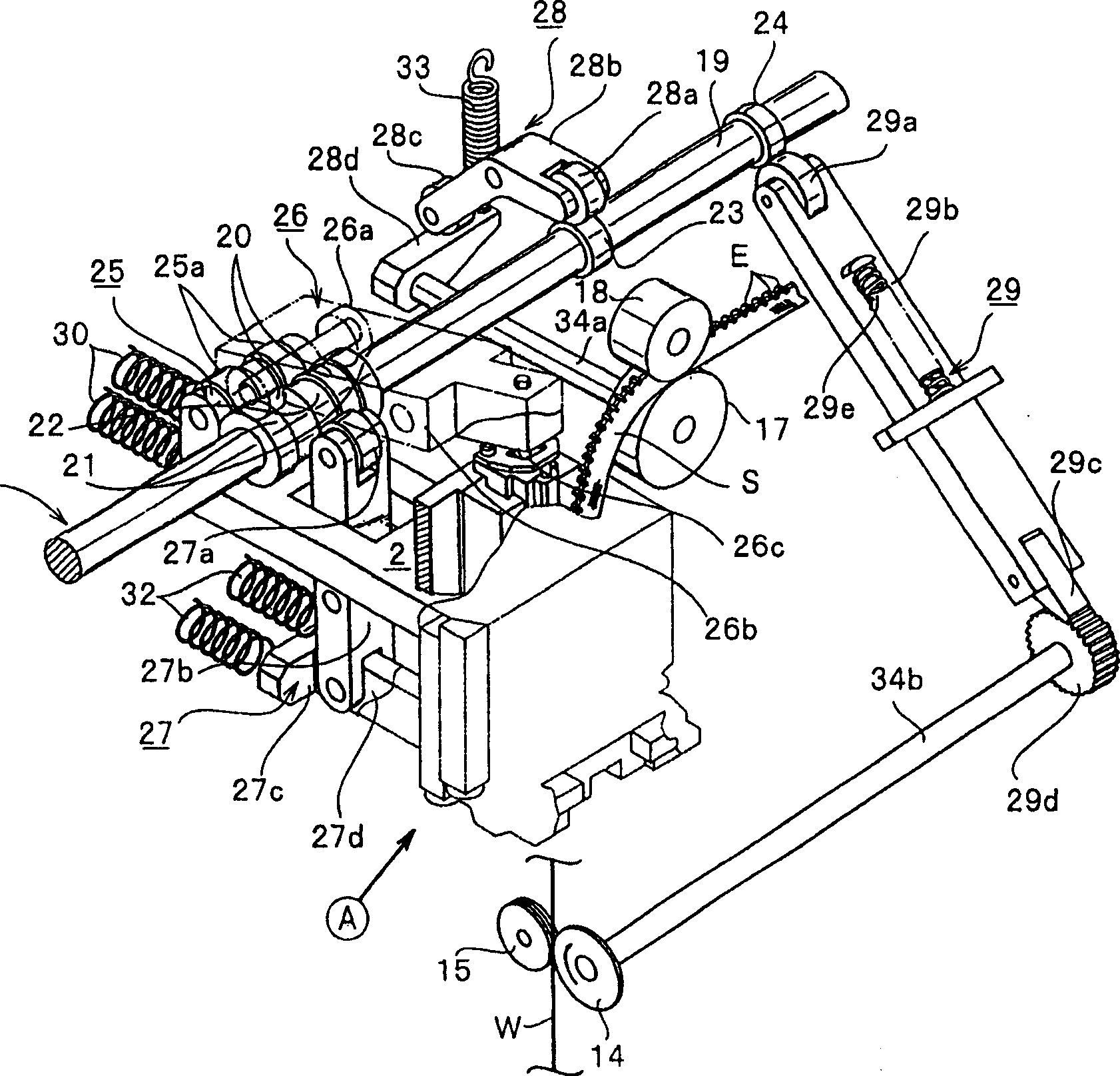
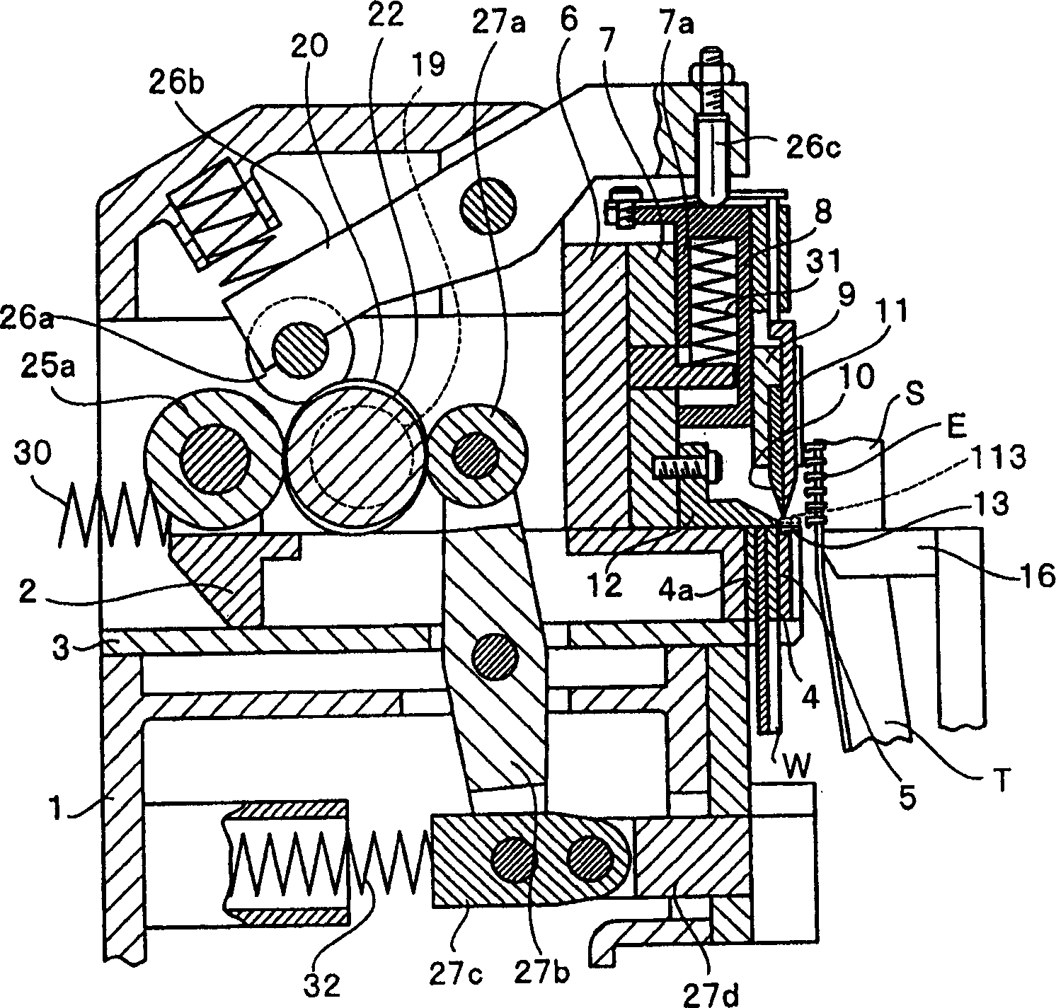
[0027] Hereinafter, preferred embodiments of the present invention will be specifically described with reference to the drawings.

[0028] Here, the method and apparatus for continuous manufacturing of a fastener chain of the present invention are not different from the conventional method and apparatus disclosed in Japanese Patent Publication No. 59-51813 in the following respect: an engagement element having a substantially Y-shaped cross-section obtained by a rolling process The wire is cut to a thickness corresponding to a single engaging element with a cutting punch, the engaging head is formed into a mountain-like shape, and then the engaging element is implanted on the required part of the zipper tape by pressing the additional leg with a pressure hammer to Continuously manufacture zipper chain.

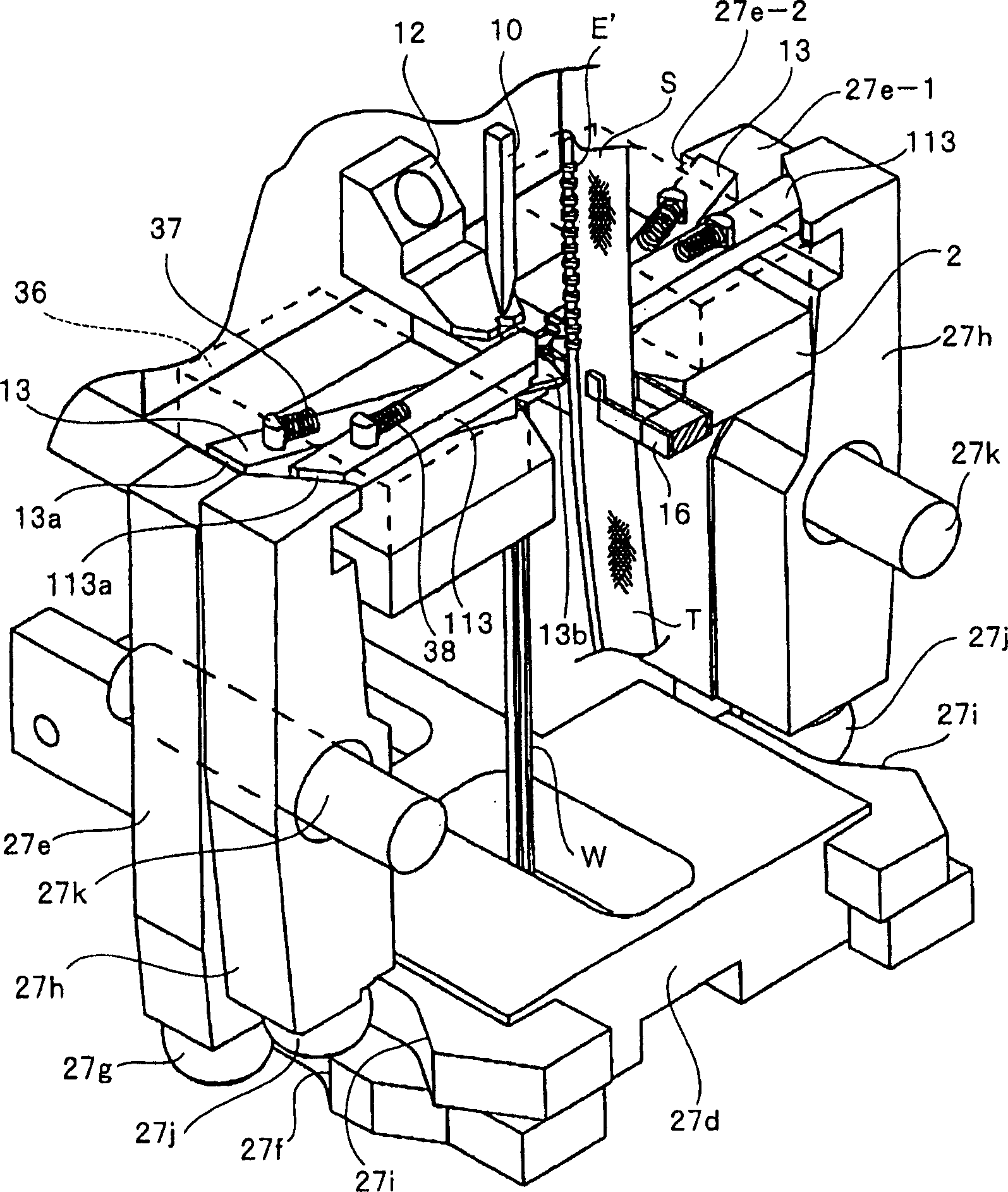
[0029] The most remarkable feature of the present invention is not that: as disclosed in Japanese Patent Application Publication No. 8-56714, when the additional leg L of the enga...


PUM


Abstract

A fastener stringer continuous manufacturing apparatus which eliminates a necessity of increasing a size of a manufacturing apparatus and is capable of chamfering attaching legs of an engaging element which is produced continuously from a metallic wire rod having a Y-shaped section, securely and accurately, without changing a load and stroke of a pressurizing hammer, the manufacturing apparatus comprises a pair of chamfering punches each of which is disposed above the pressurizing hammer at a height corresponding to a preceding engaging element implanted to a fastener tape in advance, the chamfering punch reciprocating with respect to a side face of the preceding engaging element and having a chamfering face which chamfers outer ridge portions of right and left legs of the preceding engaging element.

Description

Technical field [0001] The present invention relates to a method and equipment for continuously manufacturing a fastener stringer in which a plurality of engaging elements are implanted on one side of the fastener tape at predetermined intervals. Background technique [0002] As disclosed in, for example, Japanese Patent Publication No. 59-51813, this type of fastener chain is generally obtained as follows. That is, a long metal wire with a circular cross-section is molded into a transverse cross-section having a substantially Y-shaped shape by a plurality of rolls, and is sequentially cut with a predetermined thickness by a cutting punch and a cutting die to obtain each engaging element. The engaging head is formed into a mountain-like shape by a forming punch and a forming die, so as to obtain an engaging element including an engaging head and an additional leg (hereinafter referred to as a "wire engaging element"). Afterwards, the engaging elements are sequentially implanted o...

Claims


Application Information

Patent Timeline
Patent Type & Authority Applications(China)
IPC IPC(8): A44B19/46
CPCY10T29/49783B21D53/36A44B19/46Y10T29/53304
Inventor 井合健一郎森丘幸逸
Owner YKK CORP
Why Eureka
Try Eureka