Separation device used for grain washing
A separation device and grain cleaning technology, applied in solid separation, wet separation, chemical instruments and methods, etc., can solve the problems affecting the cleanliness of grain and incomplete separation of grain and sundries.
- Summary
- Abstract
- Description
- Claims
- Application Information
AI Technical Summary
Problems solved by technology
Method used
Image
Examples
no. 1 example
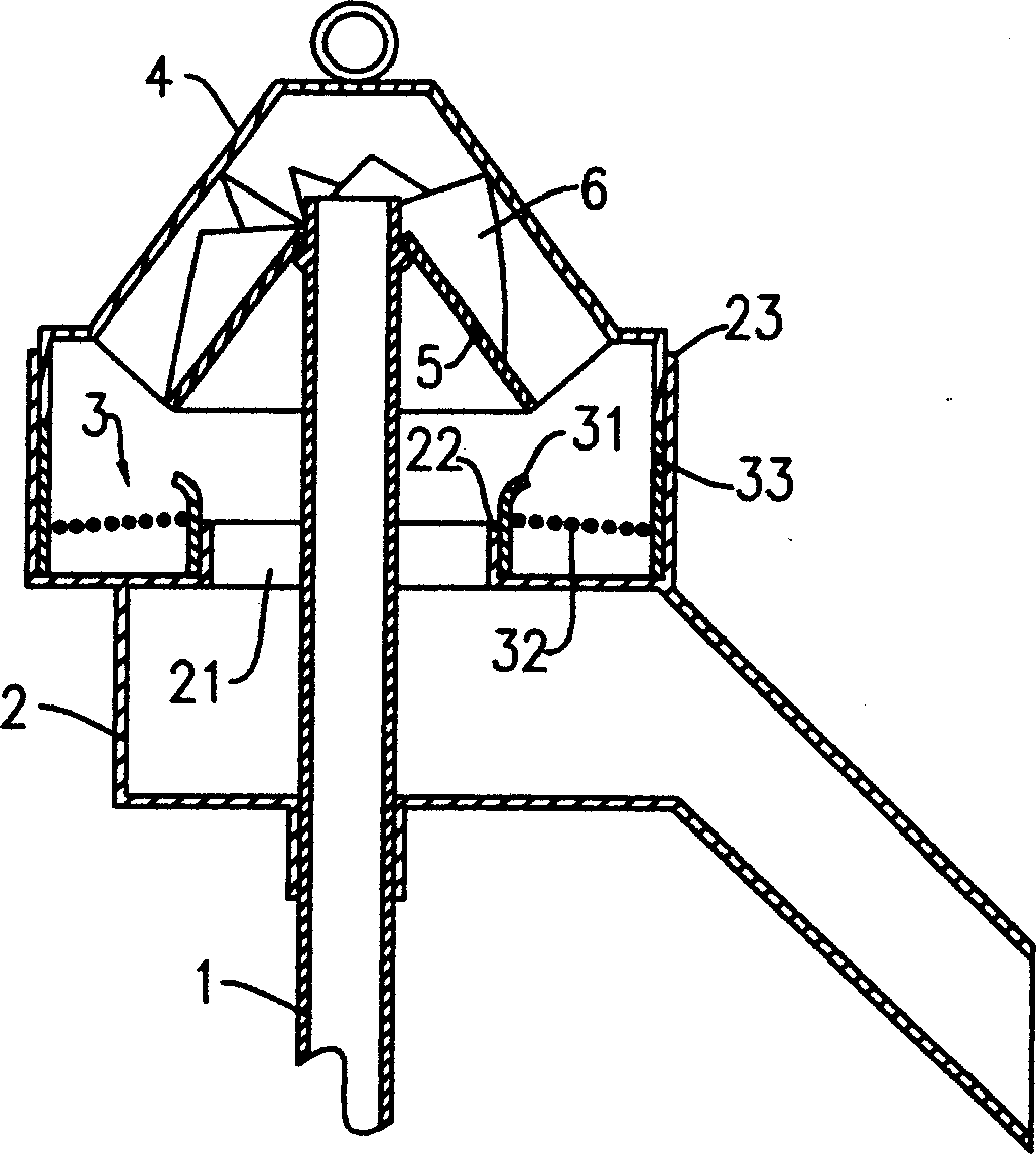
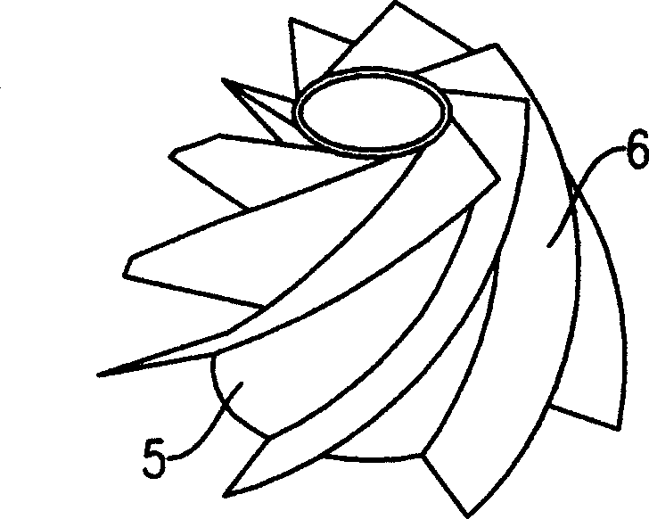
[0013] The first embodiment: as figure 1 As shown, the separation device for grain cleaning includes a discharge bin body 2 connected to the material guide pipe 1, and the top wall of the discharge bin body 2 is provided with an inner convex ring located at the return port 21 of the discharge bin 22 and an outer bead 23 located outside the inner bead 22, the space between the inner bead 22 and the outer bead 23 forms a sundry storage tank, and a filter device 3 is installed in the sundry storage tank. Described filter device 3 comprises a filter screen 32, is respectively fixed on the first raised ring 31 and the second raised ring 33 of described filter screen inner side and outer side, and described first raised ring 31 and the second raised ring 33 are connected with miscellaneous material respectively. The inner bead 22 and the outer bead 23 of the object storage tank are inserted. In order to reduce the resistance of the rotating water flow, the grid of the filter screen...
no. 2 example
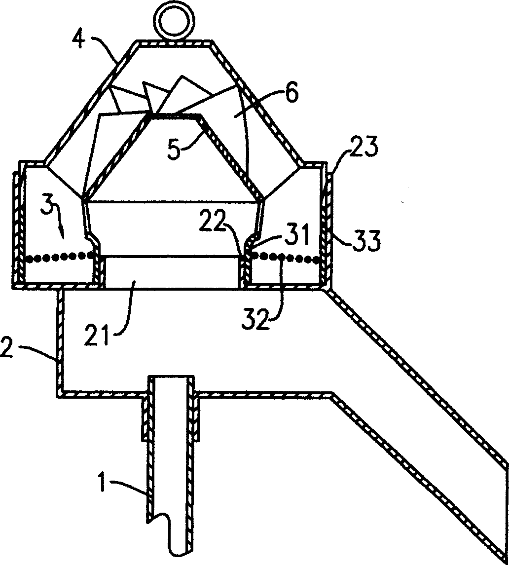
[0017] The second embodiment: as image 3 As shown, its structure is basically the same as that of the first embodiment, the difference is that the inner surfaces of the helical blades 6 are fixedly connected to the outer peripheral surface of the conical cover 5, and the bottom of the conical cover 5 is connected to the outer peripheral surface of the conical cover 5. The first protruding ring 31 of the filter device is fixedly connected, and the outer surfaces of the spiral blades 6 abut against the inner peripheral surface of the windshield 4 . Since the conical cover 5, the filter device 3 and the helical blade 6 are connected as a whole, when disassembling, the baffle cover 4 should be removed first, and then the conical cover 5, the filter device 3 and the helical blade 6 should be taken out as a whole, and the sundries should be cleaned. Storage slot.
PUM
 Abstract
Description
Claims
Application Information
 - R&D
- Intellectual Property
- Life Sciences
- Materials
- Tech Scout
- Unparalleled Data Quality
- Higher Quality Content
- 60% Fewer Hallucinations
Browse by: Latest US Patents, China's latest patents, Technical Efficacy Thesaurus, Application Domain, Technology Topic, Popular Technical Reports.
© 2025 PatSnap. All rights reserved.Legal|Privacy policy|Modern Slavery Act Transparency Statement|Sitemap|About US| Contact US: help@patsnap.com


