Original illuminating device, image access device and image forming device

A lighting device and a technology for reading originals, which are applied in the fields of original lighting devices and image reading devices, can solve the problems of deterioration of original reproducibility, poor reproducibility of originals, and large difference in image information density, etc., and achieve the effect of reducing unnecessary light beams

Inactive Publication Date: 2006-09-13
RICOH KK
View PDF4 Cites 3 Cited by
  • Summary
  • Abstract
  • Description
  • Claims
  • Application Information

AI Technical Summary

Problems solved by technology

That is, the difference in density of the image information read from the document becomes large, and the reproduction of the docume

Method used


Image

  • Original illuminating device, image access device and image forming device
  • Original illuminating device, image access device and image forming device
  • Original illuminating device, image access device and image forming device

Examples


no. 1 example

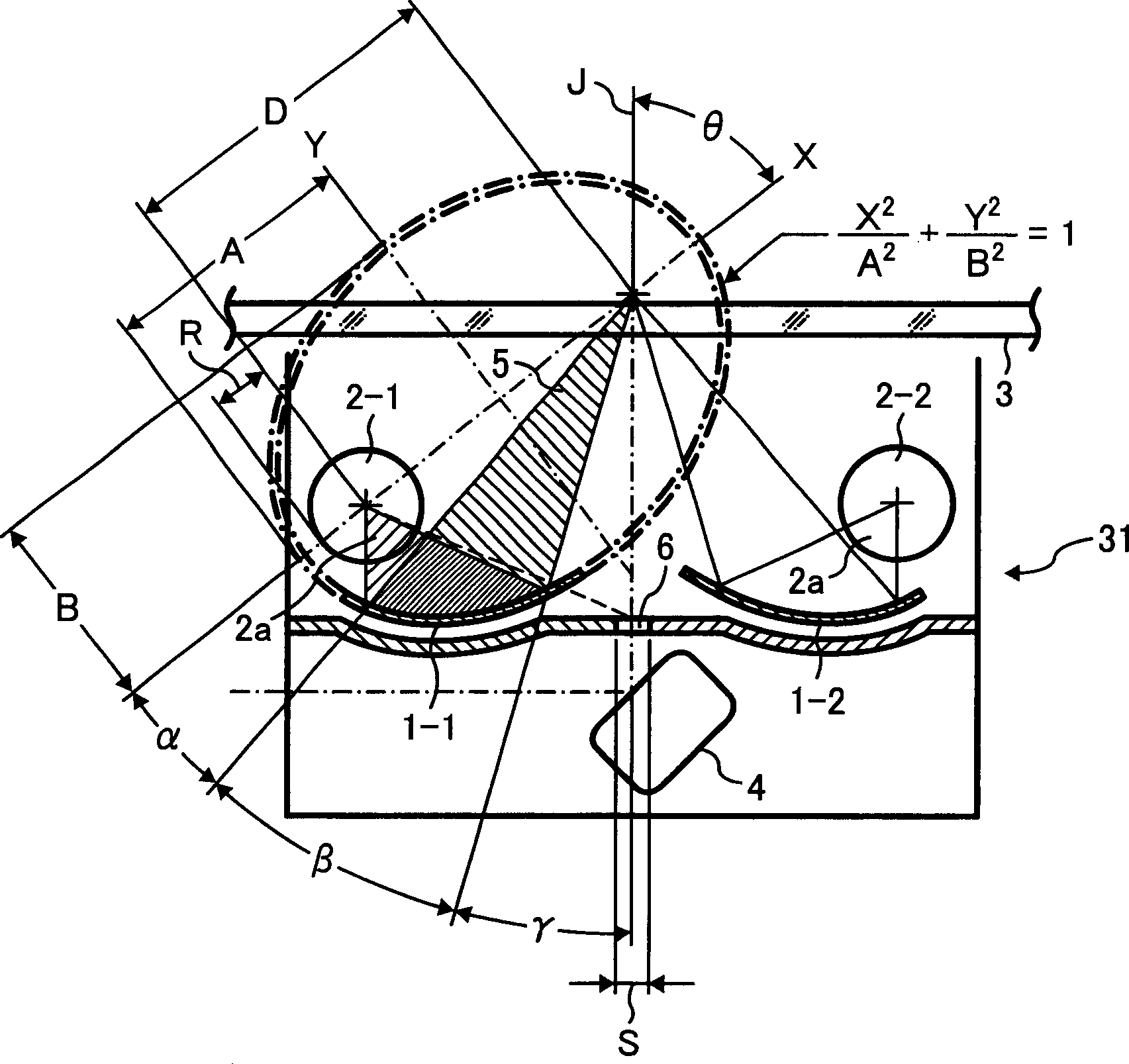
[0098] figure 2 It is a schematic sectional view of the document illuminating device provided with two fluorescent lamps according to the first embodiment of the present invention. In the document illuminating device 31 of this embodiment, the light sources 2-1, 2-2 are in the shape of long axis cylinders, and the light beams emitted from the light sources 2-1, 2-2 are reflected by the reflectors 1-1, 1-2 respectively. 2 Collect light to illuminate the document reading area of ​​the document surface placed on the platen glass 3 of the document stage. The document illuminating device 31 is provided with two fluorescent lamps (for example, Figure 8 The xenon lamp (xenon lamp) 2-1, 2-2 of structure as shown is used as light source, and it has opening, and simultaneously, is provided with two reflectors 1-1, 1-2 that are elliptical shape, respectively from two fluorescent lamps 2- 1, 2-2 light beams are collected, the openings 2a of the two fluorescent lamps 2-1, 2-2 are set to...

no. 2 example

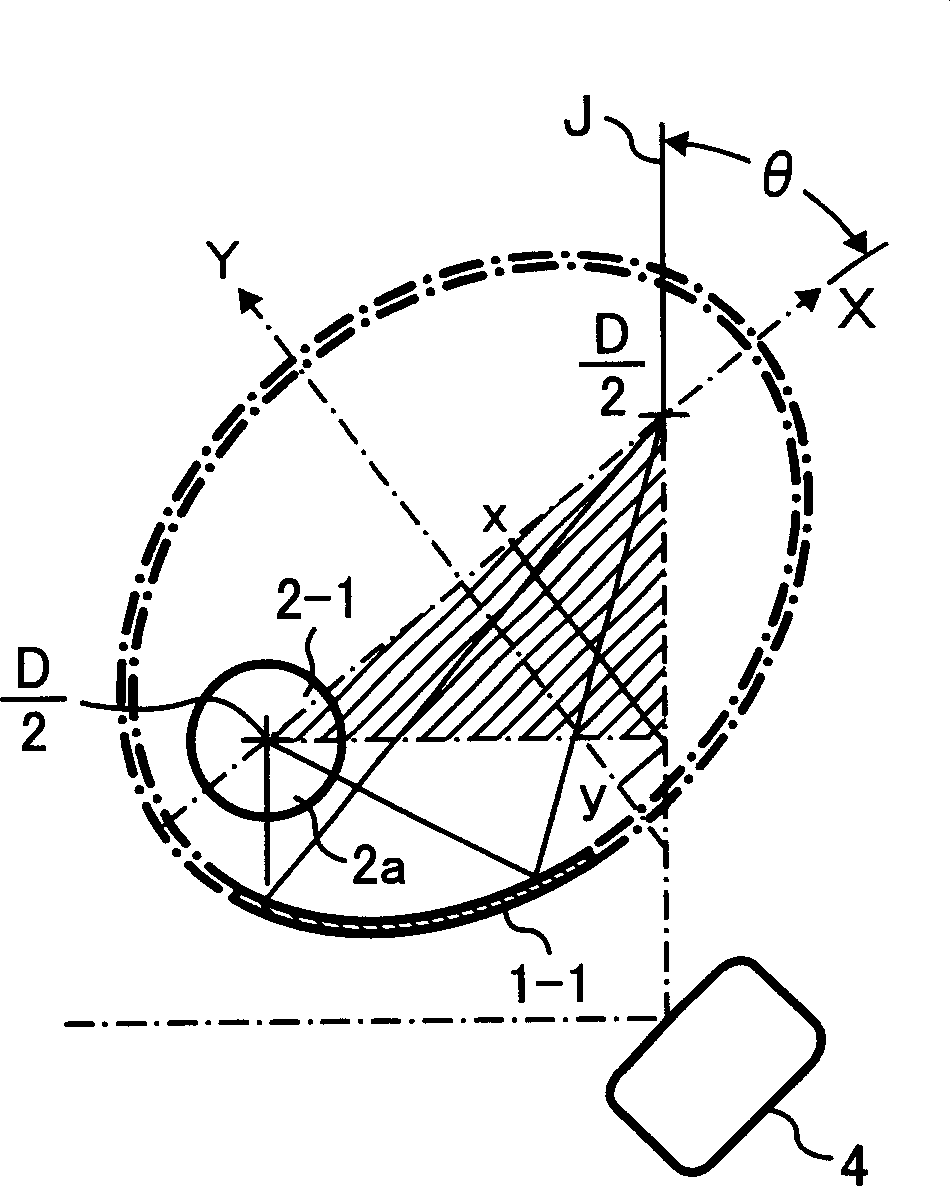
[0122] image 3 is to extract only figure 2 A schematic cross-sectional view of the elliptical reflector 1-1 and the fluorescent lamp 2-1 on the left. Here, consider a right-angled triangle ( image 3 the middle slash).

[0123] If the long axis direction of the ellipse is set as the X axis, and the short axis direction is the Y axis, then as mentioned above, the ellipse shape of the reflecting plate 1-1 can be expressed by the following formula:

[0124] X 2 A 2 + Y 2 B 2 = 1

[0125] (A>B>0)

[0126] The distance between the two foci is D, and the inclination angle of the ellipse is θ, then the Y coordinate of the apex of the right triangle is:

[0127] y = D · sin θ · ...

no. 3 example

[0133] Figure 4 It is a schematic cross-sectional view of a document illuminating device according to a second embodiment of the present invention. Figure 4 and figure 2The difference is that reflectors 1-1, 1-2 are made into an ellipse, and one focus of the ellipse (points b and c in the figure) is arranged at the following position: when the fluorescent lamps 2-1, 2-2 are connected The point on the straight line between the center and the center of the opening (position of φ / 2) and intersects the diameter of the lamp tube. Place the other focal point (point a in the figure) near the original illumination position on the optical axis. The φ is the opening angle of the fluorescent lamp.


PUM


Abstract

The invention relates to an original lighting device, a relative image reader, and an image former with said reader, wherein the original lighting device 31 has fluorescent lamps 2-1 and 2-2 as light source; the fluorescent lamp has the open part 2a that emitting light beam, the reflecting plates 1-1, 1-2 in ellipse shape, to focus the light beams of fluorescent lamps; the open part is incline downwards; the reflective plates are under the fluorescent lamps; the light beams from the open part are focused via the reflective plates to the original reading area; one focus of reflective plate is at the straight line connecting the center of fluorescent lamps and the center of open part, while another focus is near the original reading area, to avoid directly lighting said original lighting part, but only use the light reflected by reflective plates, to avoid lighting the area not needed, to avoid affecting the reflective density of original; therefore, the invention can realize high efficiency and reduce light beams.

Description

technical field [0001] The present invention relates to a document illuminating device and an image reading device using the document illuminating device, and more particularly, to a document illuminating device capable of realizing high light intensity and low flare illumination by using a fluorescent lamp as a light source, and an image reading device using the document illuminating device The device also relates to an image forming device such as a copier, a facsimile, a multifunction machine (having functions such as a copier, a printer, and a facsimile) equipped with the image reading device. Background technique [0002] For example, in JP-A-2000-307809 (hereinafter abbreviated as "Patent Document 1"), JP-A-2004-235861 (hereinafter abbreviated as "Patent Document 2"), JP-A-2003-283820 (hereinafter abbreviated as "Patent Document 2"), Denoted as "Patent Document 3"), Japanese Unexamined Publication No. P11-237699 (hereinafter abbreviated as "Patent Document 4"), and Jap...

Claims


Application Information

Patent Timeline
IPC IPC(8): H04N1/04
Inventor 三尻晋松井秀彰
Owner RICOH KK
Why Eureka
Try Eureka