Bias circuit for a wideband amplifier driven with low voltage

一种放大电路、偏置电路的技术,应用在放大装置的零部件、放大器、改进放大器以减少温度/电源电压变化等方向,能够解决不能得到放大工作等问题

Inactive Publication Date: 2006-09-27
OKI ELECTRIC IND CO LTD
View PDF0 Cites 6 Cited by
  • Summary
  • Abstract
  • Description
  • Claims
  • Application Information

AI Technical Summary

Problems solved by technology

However, this circuit has a problem that stable amplification cannot be obtained if the power supply voltage is lowered.
That is, in the conventional circuit configuration, it is difficult to achieve both an amplification operation with a sufficiently high gain in a wide frequency band and an amplification operation at a low power supply voltage.

Method used


Image

  • Bias circuit for a wideband amplifier driven with low voltage
  • Bias circuit for a wideband amplifier driven with low voltage
  • Bias circuit for a wideband amplifier driven with low voltage

Examples


Embodiment Construction

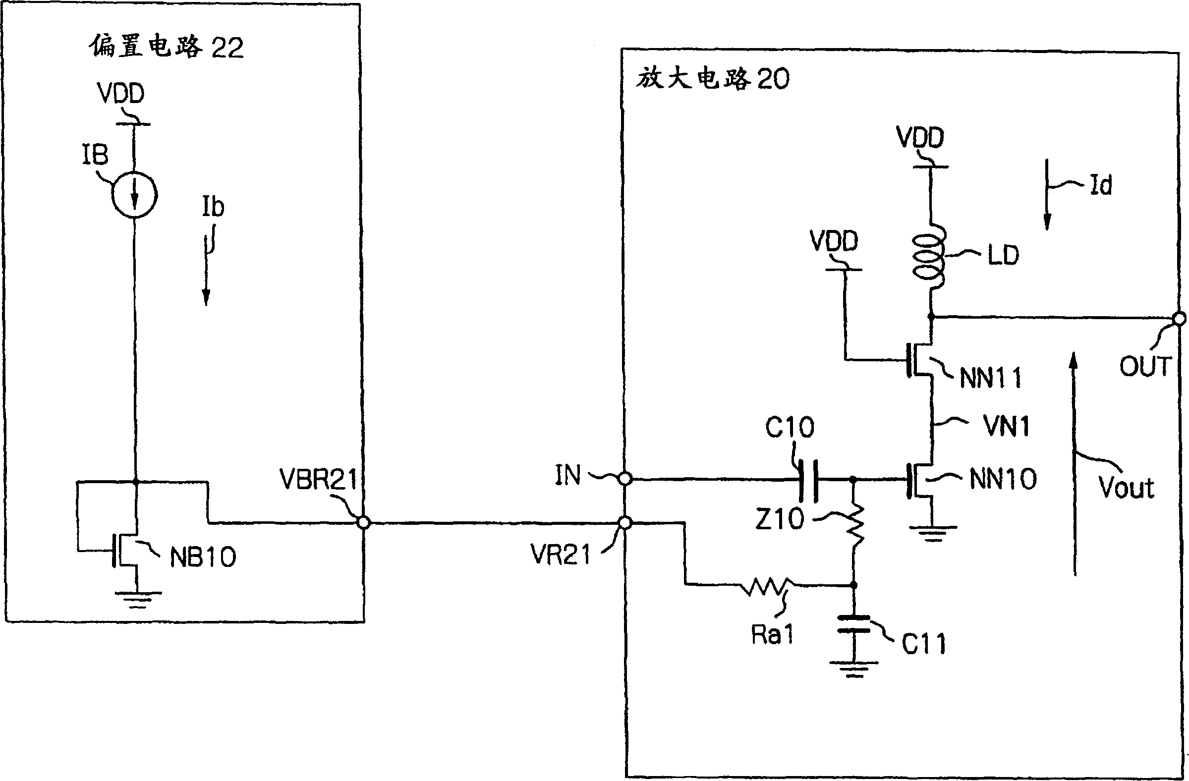
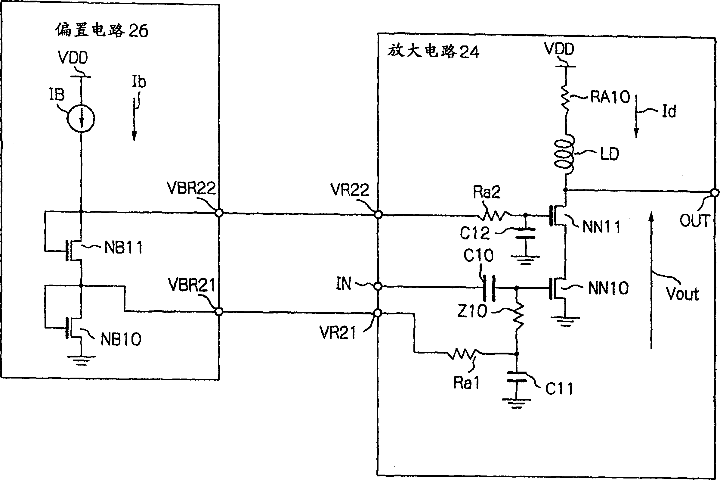
[0017] Next, an embodiment of the bias circuit for an amplifier circuit according to the present invention will be described in detail with reference to the drawings. Before the description of the embodiment of the present invention, use figure 2 A narrow-band amplifier circuit and a bias circuit for the amplifier circuit will be described as a first comparative example, using image 3 A broadband amplifier circuit and a bias circuit for the amplifier circuit will be described as a second comparative example. The second comparative example is a broadband amplifying circuit, but compared with the present invention, it is difficult to perform stable amplifying operation when the power supply voltage is lowered.

[0018] figure 2 It is a cascode high-frequency amplifier circuit that can be used in the narrow frequency band of the first comparative example, and is composed of an amplifier circuit 20 and a bias circuit 22 . The amplifier circuit 20 includes, for example, an NM...


PUM


Abstract

An amplifier includes a ground, first and second MOS transistors, a first resistive load and a supply voltage, which are connected in series in this order. A bias circuit provides first and second bias voltages to the gate electrodes of the first and second transistors, respectively. The bias circuit includes a third MOS transistor having its gate and drain electrode diode-connected. The drain electrode of the third transistor provides the first bias voltage of the amplifier. The bias circuit further includes fourth and fifth MOS transistors, and a second resistive load, which are connected in series in this order. The second resistive load is connected to the supply voltage. The fourth transistor has its gate electrode connected to the drain electrode of the third transistor. The fifth transistor has its gate and drain electrodes diode-connected. The drain electrode of the fifth transistor provides the second bias voltage.

Description

technical field [0001] The present invention relates to a bias circuit for supplying a bias voltage to a high-frequency amplifying circuit. This circuit can also be applied to a bias circuit for an amplifying circuit called UWB (Ultra Wideband) that requires a wide-band operation of 500 MHz or more , can work with low voltage and low power consumption. Background technique [0002] As a conventional example of a high-frequency amplifier circuit used in a narrow band, there is an example shown in Non-Patent Document 1, for example. Examples of cascode amplifier circuits for improving high-frequency characteristics are shown on p.164 to 166 of Non-Patent Document 1, and examples of amplifier circuits exemplifying element constants are shown on p.288 to 292. [0003] In addition, as a conventional example of a high-frequency amplifier circuit used in a broadband, there is an example shown in Non-Patent Document 2, for example. Regarding the quality coefficient as an index ind...

Claims


Application Information

Patent Timeline
Patent Type & Authority Applications(China)
IPC IPC(8): H03F1/42
CPCH03F3/345H03F1/086H03F1/223H03F1/301H03F3/04H03F3/45183H03F2200/36H03F2203/45508H03F1/30
Inventor 田野井聪
Owner OKI ELECTRIC IND CO LTD
Why Eureka
Try Eureka