Liquid container

A liquid container and liquid technology, applied in printing and other directions, can solve the problems of cost increase, cost increase, assembly characteristic deterioration, etc., to achieve the effect of preventing consumption, preventing liquid leakage, and improving assembly performance

Inactive Publication Date: 2006-10-04
SEIKO EPSON CORP
View PDF3 Cites 9 Cited by
  • Summary
  • Abstract
  • Description
  • Claims
  • Application Information

AI Technical Summary

Problems solved by technology

Thus, an increase in the components of the air cavity leads to deterioration of assembly characteristics and an increase in cost
[0011] In addition, in the case where the air chamber is provided on the printer side, it is necessary to airtightly connect the air opening passage between the printer and the ink cartridge, whereby for example, the formation of the connection structure increases the cost

Method used


Image

  • Liquid container
  • Liquid container
  • Liquid container

Examples


Embodiment Construction

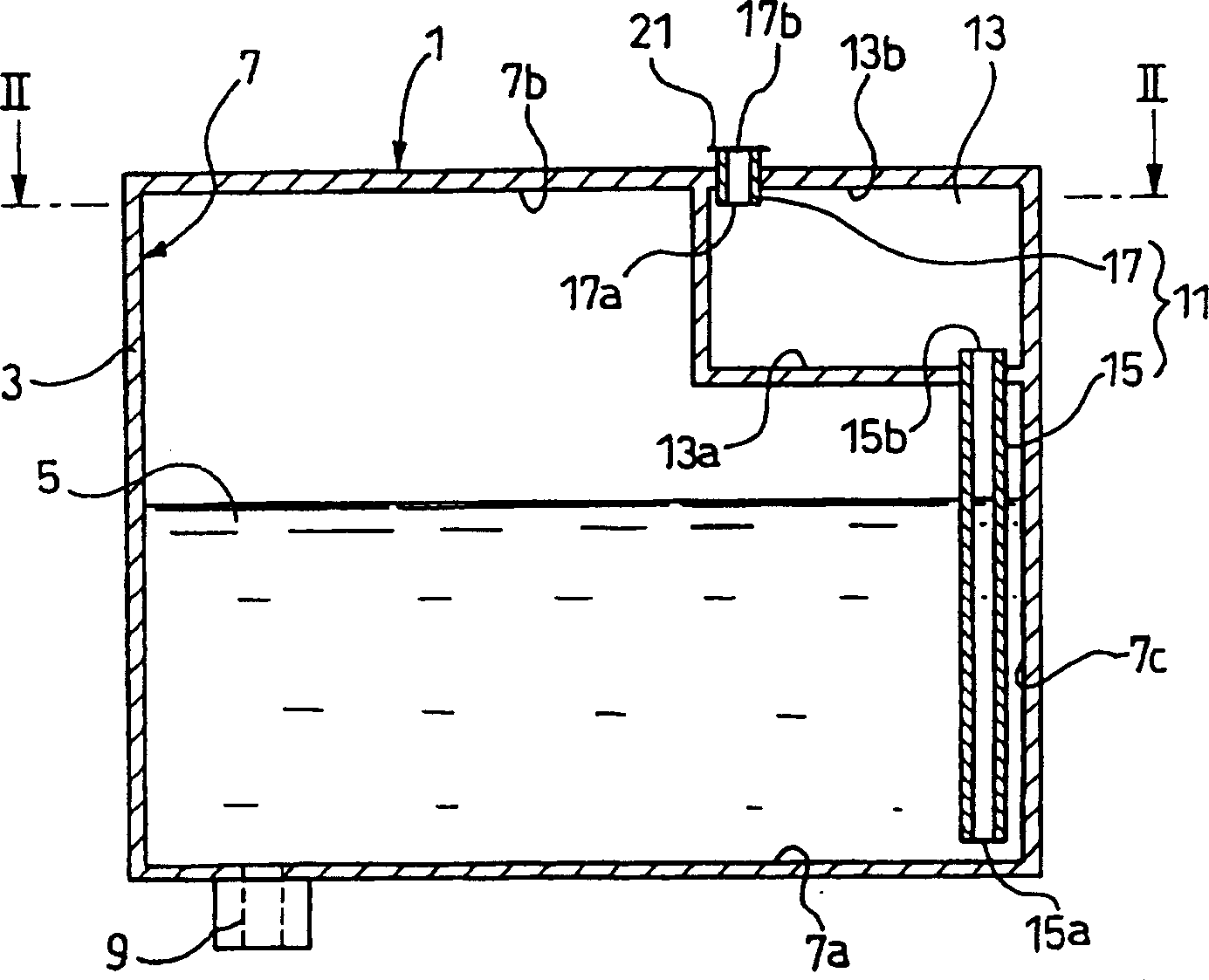
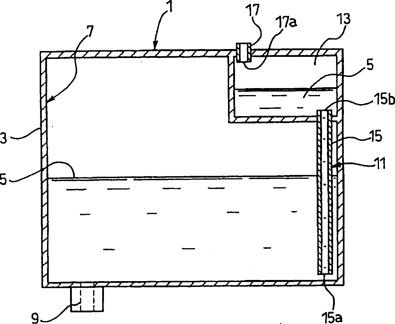
[0054] Figure 1 to Figure 5 An ink cartridge according to a first embodiment of the liquid container of the present invention is shown. figure 1 is a longitudinal sectional view showing a schematic structure of the ink cartridge according to the first embodiment. figure 2 is along figure 1 The sectional view taken by the line II-II in . image 3 An illustrative diagram showing that due to the thermal expansion of air, figure 1 The ink cartridge is shown in a state where the ink in the liquid chamber flows back into the lower open passage and is stored in the air chamber. Figure 4 is a cross-sectional view showing where figure 1 The ink cartridge is shown in a state in which the ink cartridge has fallen sideways toward one side, and the ink in the liquid chamber has flowed into the air chamber. Figure 5 is a cross-sectional view showing that when figure 1 Ink cartridge orientation shown Figure 4 The state of the ink in the liquid chamber when the opposite side of th...


PUM


Abstract

A liquid container has an air open passage for causing a liquid chamber to communicate with an outside and introducing outside air into the liquid chamber as liquid in the liquid chamber is consumed, and an air chamber provided in a portion of the air open passage and capable of storing the liquid entering the air open passage. The air open passage includes a lower open passage having one end opened to the liquid chamber at a position close to an internal surface of a bottom wall of the liquid chamber and the other end opened to the air chamber at a position close to an internal surface of a bottom wall of the air chamber, and an upper open passage having one end opened to the air chamber at a position close to an internal surface of a ceiling wall of the air chamber and the other end capable of being opened to the outside.

Description

technical field [0001] The present invention relates to a liquid container including an air cavity capable of storing liquid entering an air open passage of a container body detachably attached to a container mounting portion on a device side. Background technique [0002] Examples of liquid containers include ink cartridges for inkjet type printers. In an ink cartridge for an inkjet type printer, an ink chamber containing ink to be supplied to a print head is provided in a container body. In use, the ink cartridge is detachably assembled and mounted to the cartridge mounting portion at a predetermined position. Ink contained in the ink chamber is supplied to the print head to be driven according to print data transmitted from the host, and ejected from nozzles provided on the print head on a target position of a print medium such as paper. [0003] Various air-opening type ink cartridges mountable to inkjet printers have been proposed, in which a container body to be deta...

Claims


Application Information

Patent Timeline
Patent Type & Authority Applications(China)
IPC IPC(8): B41J2/175B41J2/18
Inventor 石泽卓品田聪
Owner SEIKO EPSON CORP
Why Eureka
Try Eureka