Engine carrier and shock-absorbing bearing structure employing the carrier

A technology for engine mounts and mounting components, which is applied in power units, transportation and packaging, non-rotational vibration suppression, etc., can solve problems such as increased production costs, difficulty in adoption, and large installation space, so as to reduce production costs and avoid adverse effects , the effect of a simple structure

Active Publication Date: 2006-10-04
TOKAI RUBBER IND LTD
View PDF2 Cites 30 Cited by
  • Summary
  • Abstract
  • Description
  • Claims
  • Application Information

AI Technical Summary

Problems solved by technology

However, this places the risk of adversely affecting the damping performance of the power plant, which is required in the first place, and this arrangement is difficult to implement in practice
It is also conceivable to reduce the vibration of the vehicle body in the prob

Method used


Image

  • Engine carrier and shock-absorbing bearing structure employing the carrier
  • Engine carrier and shock-absorbing bearing structure employing the carrier
  • Engine carrier and shock-absorbing bearing structure employing the carrier

Examples


Embodiment Construction

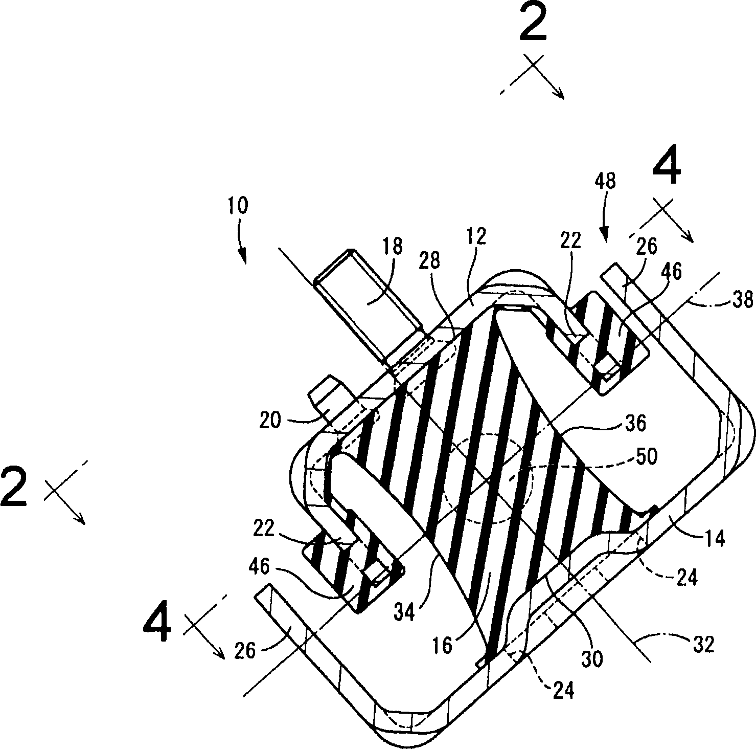
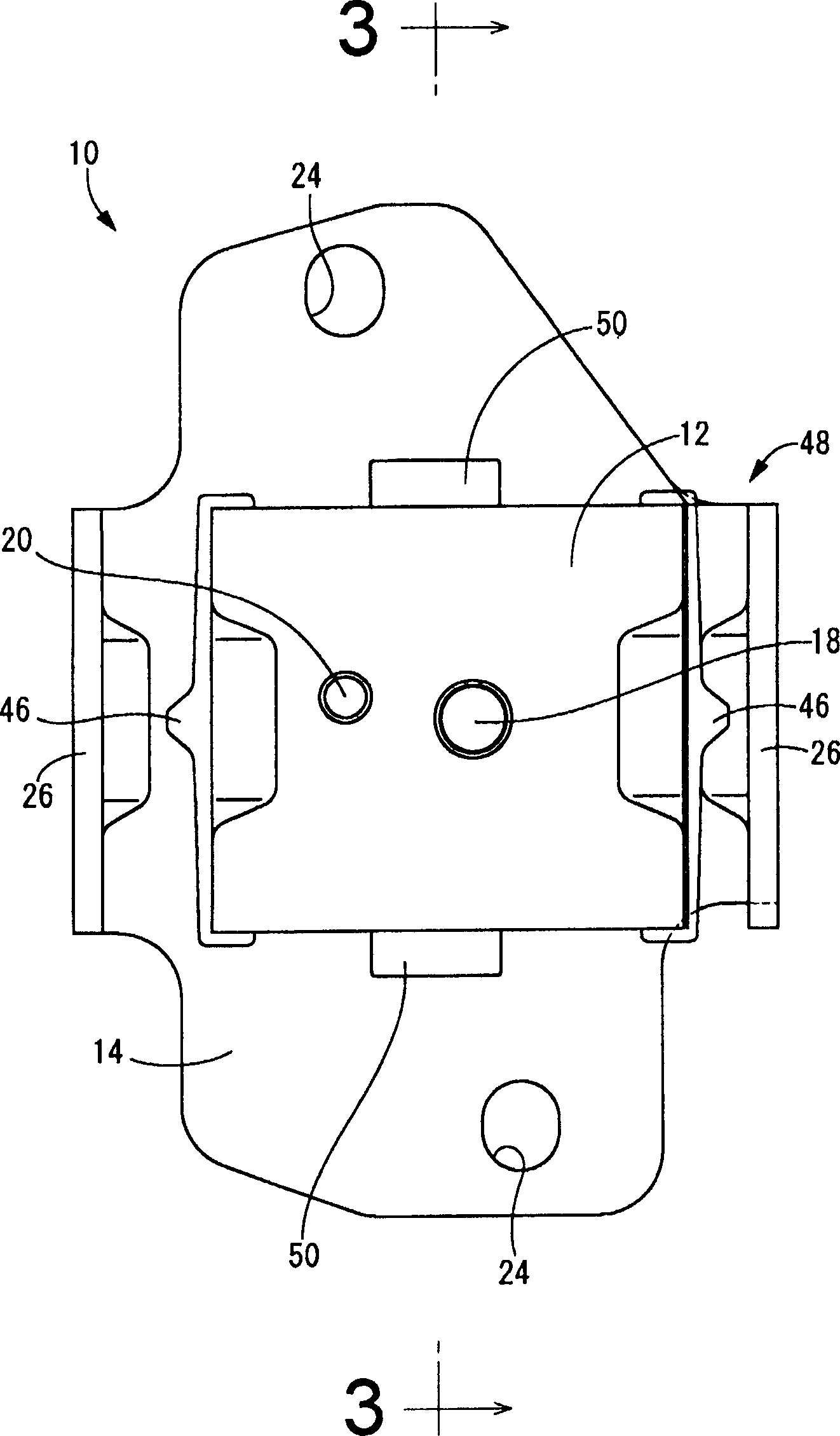
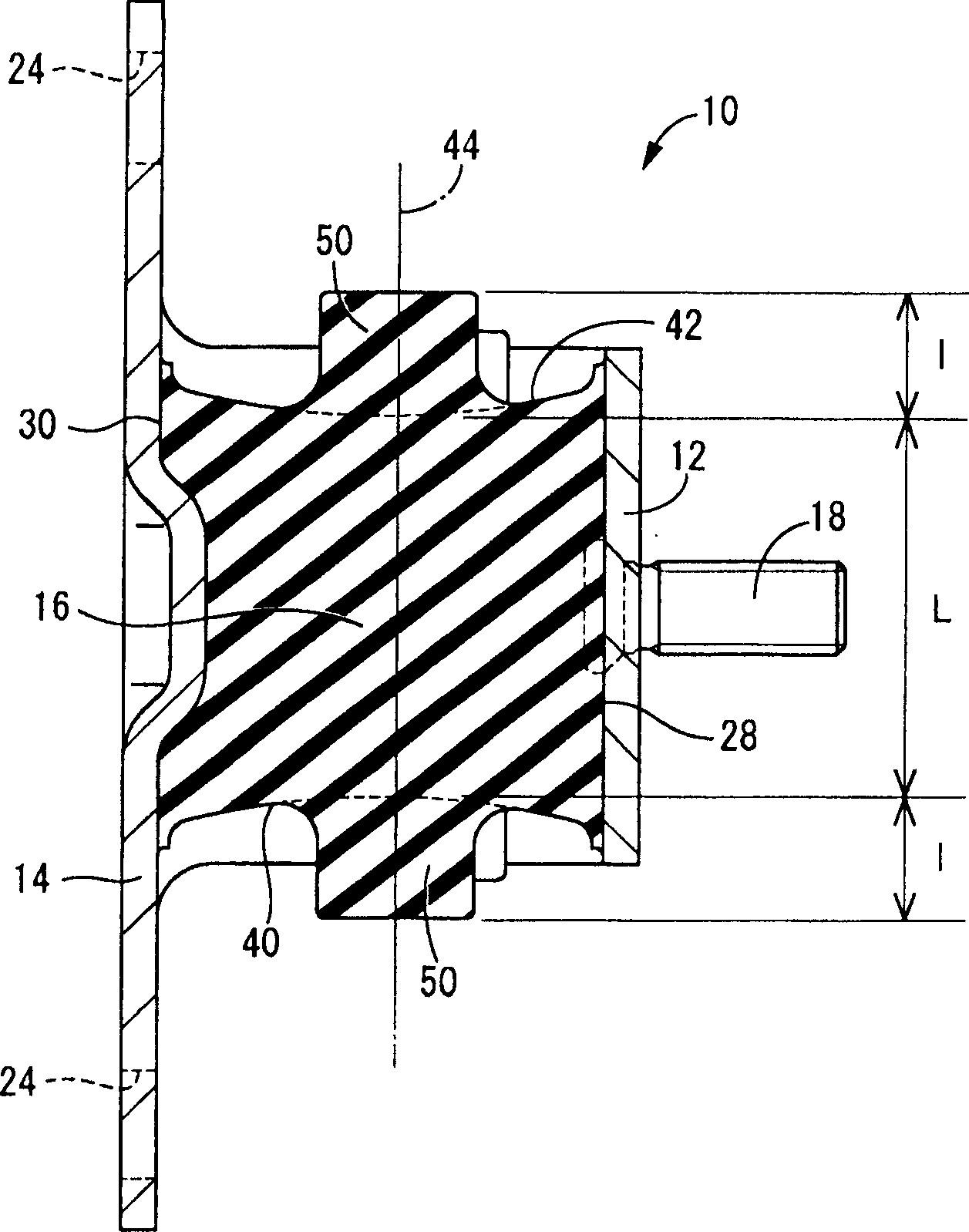
[0032] first reference Figure 1-4 , which shows an engine mount 10 according to an embodiment of the present invention. The engine mount 10 includes a metal upper mounting member 12 and a metal lower mounting member 14 separated by a predetermined distance and connected together with a main rubber elastic body 16 therebetween. In the following descriptions, unless otherwise stated, the vertical direction refers to the figure 1 in the up-down / vertical direction.

[0033] More specifically, the upper mounting member 12 has a generally rectangular flat plate shape and is made of a rigid material such as metal or the like. A fastening bolt 18 protruding therefrom is integrally formed near the center of the upper mounting member 12 , and a generally cylindrical protrusion 20 with a small diameter protrudes at a position off the center.

[0034] In the transverse direction of the upper mounting member 12 ( figure 2 A pair of upper stopper portions 22 are integrally formed at b...


PUM


Abstract

The invention relates to an engine base (10), which comprises: a main rubber elastic body (16) in rectangle shape; an upper and lower mounting elements (12, 14) fixed on the top and bottom (28, 30) of rubber elastic body, wherein said base extends along the separated direction of front and back end surfaces (40, 42), to be mounted incline with front-back axle (32); the left-right axle (38) extending along the separated direction of top-bottom axle (32) at top and bottom and at the separated direction of left and right end surfaces (34, 36) is incline with the vertical axle and horizontal axle; one couple of block protrusions (50) that protrude from the central part of front and back end surfaces along the front-back axle to be integrated with elastic body. The invention also provides a vibration-reduction support with said engine base.

Description

[0001] combined reference [0002] The disclosure of Japanese Patent Application No. 2005-096256 filed on Mar. 29, 2005 - including specification, drawings and abstract - is hereby incorporated by reference in its entirety. technical field [0003] The present invention relates to an engine mount in which a power unit of an automobile is supported in a vehicle body in a vibration-damping manner, and to a support structure for supporting the power unit on the vehicle body using the engine mount. Background technique [0004] In general automobiles, the mechanism for supporting the power unit on the vehicle body is realized by rubber mounts called engine mounts. By elastically supporting the power unit on the vehicle body with a plurality of rubber mounts, transmission of vibration from the power unit to the vehicle body can be reduced. [0005] One of such engine mounts known in the prior art employs a main rubber-elastic body in the form of a solid rectangular block. For e...

Claims


Application Information

Patent Timeline
IPC IPC(8): F16F15/08B60K5/12
Inventor 铃木真悟德本润一
Owner TOKAI RUBBER IND LTD
Why Eureka
Try Eureka