Magnetic levitation train mounted with vortex brake

A technology of eddy current brakes and magnetic levitation, applied in the direction of brake types, drum brakes, combined drum brakes, etc., can solve the problems of vehicle speed reduction, mechanical anchor damage, increase, etc.

Active Publication Date: 2006-10-04
THYSSENKRUPP TRANSRAPID
View PDF3 Cites 15 Cited by
  • Summary
  • Abstract
  • Description
  • Claims
  • Application Information

AI Technical Summary

Problems solved by technology

The disadvantage is that the normal force additionally generated by the braking magnet vertically against the reaction rail increases as the vehicle speed decreases, especially if the eddy current brake is adjusted to a constant braking force and thus requires a larger current to maintain the desired braking force, the vehicle speed decreases even more
Consequently, the forces acting on the reaction rails increase so much that they exceed permissible critical values ​​and thus may cause damage to the mechanical anchoring of the reaction rails

Method used


Image

  • Magnetic levitation train mounted with vortex brake
  • Magnetic levitation train mounted with vortex brake
  • Magnetic levitation train mounted with vortex brake

Examples


Embodiment Construction

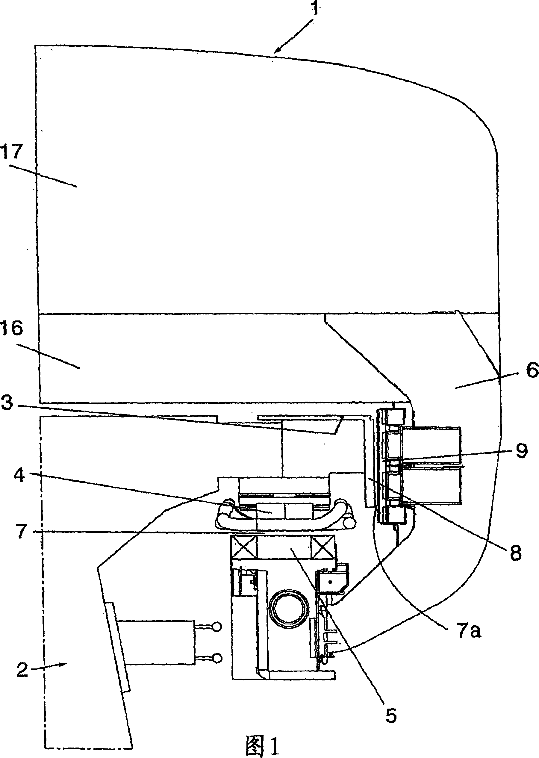
[0013] Figure 1 schematically represents a cross-section through a magnetically levitated vehicle 1 conventionally movably mounted on guide rails extending in the longitudinal direction of the route, said guide rails comprising supports made of steel and / or concrete 32 and the rail plate 3 installed thereon. The thrust of the magnetically levitated vehicle 1 is achieved, for example, by a long stator motor comprising stator laminations 4 attached below said rail plate 3 and arranged continuously in its longitudinal direction. The stator laminations 4 have an alternating succession of teeth and slots, not shown here, into which windings supplied with three-phase currents of variable amplitude and frequency are inserted. The actual excitation field of the long stator motor is generated by at least one carrying magnet 5 attached to said maglev vehicle 1 by at least one transverse bracket 6 and having poles facing downwardly open slots of the stator laminations 4, As shown in Fig...


PUM


Abstract

The invention relates to a magnetic levitation railway provided with an eddy-current brake (20) interacting with a reaction rail (8) of a travel way (2). Said invention is characterised in that said eddy-current brake (20) comprises at least one brake magnet which is movably mounted on a vehicle (16) in a perpendicular direction with respect to the reaction rail (8) and is applied thereto when a normal force exceeds a value determined, for example by a springs (27).

Description

technical field [0001] The invention relates to a magnetically levitated railway of the kind stated in the preamble of claim 1 and to a magnetically levitated vehicle for such a railway. Background technique [0002] Known maglev railways of this type are driven, for example, by long-stator linear motors provided with three-phase AC windings located in long stators alongside the guide rails. The excitation field of the linear motor is supplied by a support magnet which simultaneously acts as an excitation magnet and is arranged in the vehicle (DE 3919058 C2). In addition to driving, linear motors can also be used to brake the vehicle. For this purpose, it is only necessary to supply the three-phase AC windings of the associated long stator with a current having a sign opposite to that of normal operation during driving. [0003] Since there is no possibility of braking when e.g. individual magnets or all supporting and exciting magnets fail to work, magnetically levitated ...

Claims


Application Information

Patent Timeline
Patent Type & Authority Applications(China)
IPC IPC(8): B60L7/28F16D65/14F16D53/00B61H7/08B60L13/10F16D63/00
CPCB61H7/083F16D63/008B60L13/10B60L7/28B60L2200/26F16D2121/20
Inventor S·孔茨
Owner THYSSENKRUPP TRANSRAPID
Why Eureka
Try Eureka