
Tower for a wind power station

A technology for wind energy equipment and towers, applied in mechanical equipment, wind power generation, towers, etc., can solve problems such as technical requirements

Active Publication Date: 2006-10-04
SIEMENS GAMESA RENEWABLE ENERGY SERVICE GMBH
View PDF2 Cites 30 Cited by
  • Summary
  • Abstract
  • Description
  • Claims
  • Application Information

AI Technical Summary

Problems solved by technology

[0007] But the problem brought in this case is the transition from shell structure (tubular column) to lattice structure (lattice column), because it is technically very demanding

Method used


Image

  • Tower for a wind power station
  • Tower for a wind power station
  • Tower for a wind power station

Examples


Embodiment Construction

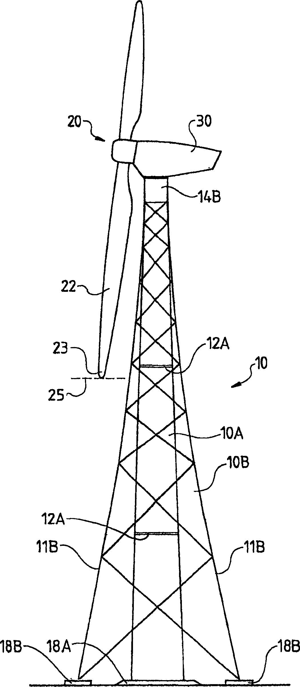
[0074] figure 1A wind energy installation according to the prior art is shown, in which two tower variants, namely a tubular tower 10A and a lattice tower 10B, are shown superimposed as supporting towers 10 . The tower 10 supports a machine nacelle (Maschinengondel) 30 rotatably fixed about a vertical tower axis, on which a machine including at least one blade tip 23 is supported rotatably about a substantially horizontal axis. The rotor blades 22 of the rotor 20 . The figure shows a design of a three-blade rotor, wherein the horizontal plane of the rotor tip 23 in the lower position is indicated by a dashed line 25 .

[0075] In addition to the rotor support, the machine nacelle 30 generally contains a generator, if necessary a transmission, a wind tracking system, various electrical components and other auxiliary systems. These components have not been shown for clarity of view.

[0076] The tubular tower 10A has a plurality of flange connections 12A for shipping reasons....


PUM


Abstract

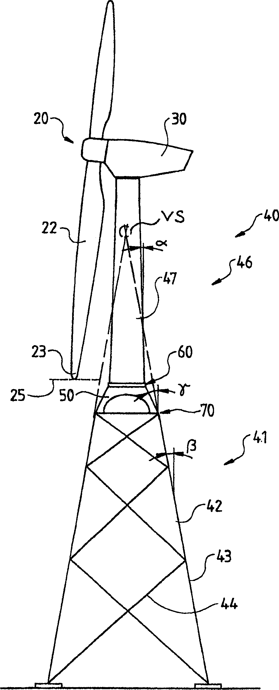
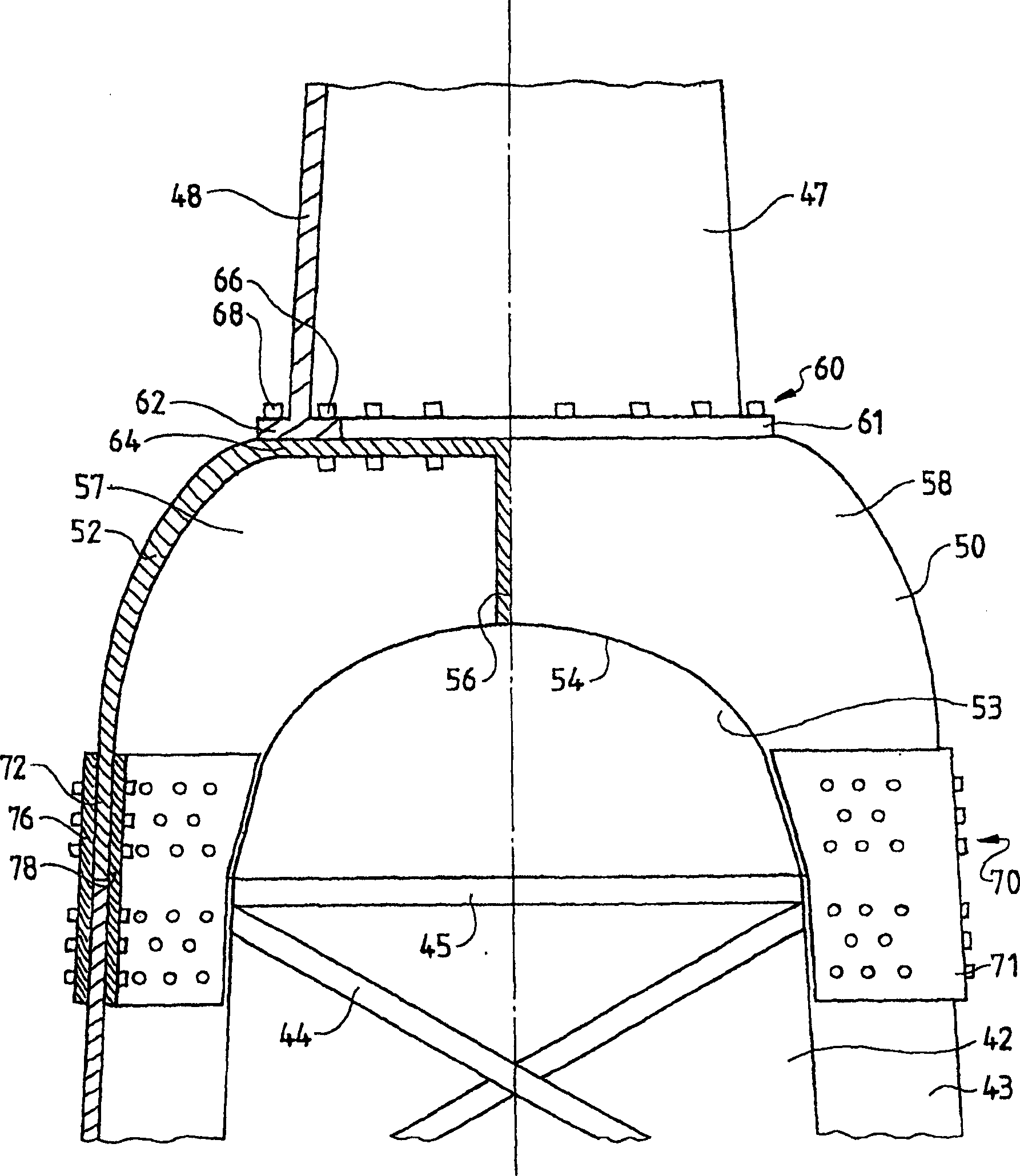
Disclosed is a tower for a wind power station comprising a machine pod disposed on the tower and a rotor mounted on the machine pod so as to be rotatable about an essentially horizontal axis. Said rotor is provided with at least one blade. The tower is composed of a tubular upper section that is connected to a lower section which is embodied as a lattice tower in a transition zone. The lattice tower encompasses at least three corner posts. The upper tower section forms at least one sixth of the entire tower. The cross section of the lower tower section below the transition zone is greater than the cross section of the upper tower section while the transition zone is configured such that the cross section of the lower tower section is adjusted to the cross section of the upper tower section so as to optimize power flux.

Description

technical field [0001] The invention relates to a tower for a wind energy installation. Background technique [0002] Contemporary wind energy installations consist mainly of tubular towers, especially steel pipe towers, since this type of construction, known as shell construction, is the simplest and most economical tower construction. For large wind energy installations with rotor diameters of more than 70 m and tower heights of more than 80 m and powers greater than 1.5 MW, the required tower diameter in the lower area of ​​the tower is a decisive technical limit. Diameters over 4.3m are difficult to transport as often the underpass clearance height does not allow larger dimensions. In addition, the overall length and mass of the column must be divided into a plurality of column sections, which are each screwed to one another by means of annular flange connections. These large ring flange connections represent an expensive cost factor in addition to logistical transport...

Claims


Application Information

Patent Timeline
Patent Type & Authority Applications(China)
IPC IPC(8): E04H12/08F03D11/04
CPCE04H2012/006Y02E10/728F05B2240/9121F05B2240/40F03D11/04E02D27/42F05B2240/912E02B17/027E02B2017/006E02B2017/0091F03D13/20E02D27/425F03D9/255F03D80/85Y02E10/72
Inventor R·魏特坎普U·欣茨S·舍费尔
Owner SIEMENS GAMESA RENEWABLE ENERGY SERVICE GMBH
Learn More