Three-point bending beam type apparatus for big size material damping test
A three-point bending beam and material damping technology, which is applied in the direction of measuring devices, elastic testing, machine/structural component testing, etc., can solve the problems of inability to test the damping performance of large-scale materials, achieve simple structure, improve measurement accuracy, The effect of easy installation
- Summary
- Abstract
- Description
- Claims
- Application Information
AI Technical Summary
Problems solved by technology
Method used
Image
Examples
specific Embodiment approach 1
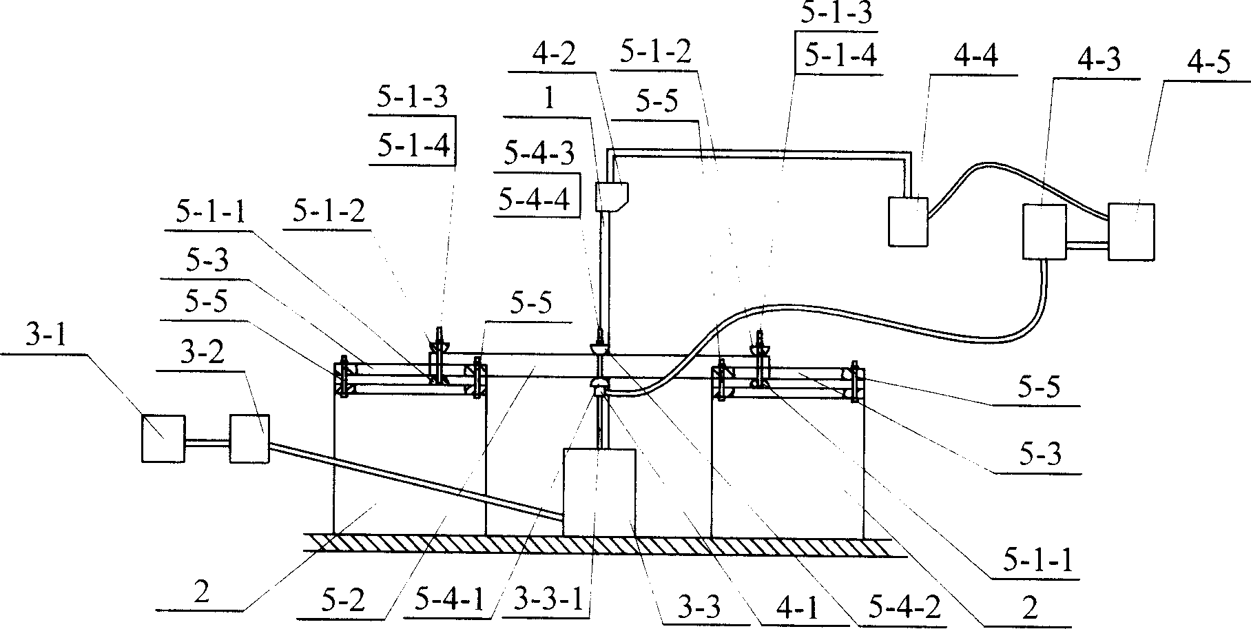
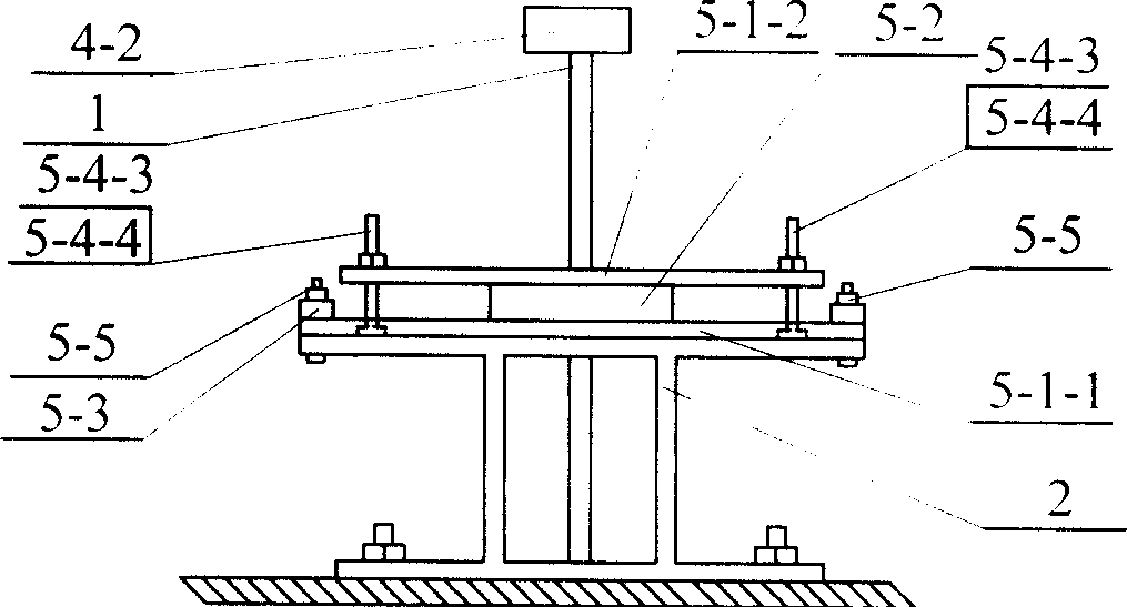
[0011] Specific implementation mode one: combine figure 1 , figure 2 Describe this embodiment. This embodiment consists of two bases 2 placed relatively parallel and fixedly connected to the ground, a bracket 1 located between the two bases 2 and fixedly connected to the ground, an excitation system, a measurement system, and a three-point bending beam The device is composed of; the three-point bending beam device is composed of two hinge supports, a three-point bending beam 5-2, a pressure beam 5-3, a loading head, and a connector 5-5; the excitation system is composed of a signal generator 3-1, a power amplifier 3-2, and an exciter 3-3 fixedly connected to the ground; the measurement system is composed of a force sensor 4-1, a displacement sensor 4-2, a charge amplifier 4-3, and a voltage amplifier 4-4. The data collector 4-5 consists of a hinge support placed on each base 2, and one end of the three-point bending beam 5-2 is fixedly mounted on one of the two hinge support...
specific Embodiment approach 2
[0014] Specific implementation mode two: combination figure 1 Describe this embodiment, each hinge support in the two hinge supports of this embodiment is respectively made up of lower semicircular member 5-1-1, upper semicircular member 5-1-2, screw rod 5-1- 3. The nut 5-1-4 is composed; the upper semicircular member 5-1-2 is placed directly above the lower semicircular member 5-1-1, and the arc surface of the upper semicircular member 5-1-2 Placed opposite to the arc surface of the lower semicircular member 5-1-1, the two ends of the three-point bending beam 5-2 are respectively mounted on the upper semicircular member 5-1-2 of each hinge support Between the upper semicircular member 5-1-2 and the lower semicircular member 5-1-1 through the screw rod 5-1-3 and the nut 5-1-4 Fixed connection. In order to realize the adjustable vertical dimension of the three-point bending beam 5-2, each hinge support is connected with a screw 5-1-3 and fixed with a nut 5-1-4. In order to r...
specific Embodiment approach 3
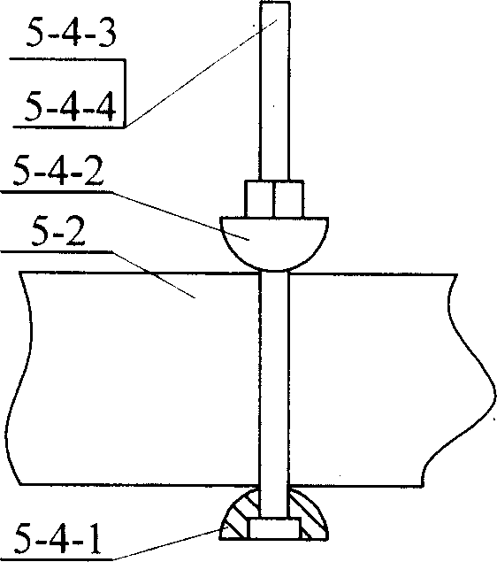
[0015] Specific implementation mode three: combination figure 1 , image 3 , Fig. 4 illustrates the present embodiment, and the loading head of the present embodiment is made of upper semicircular steel bar 5-4-2, lower semicircular steel bar 5-4-1, connecting screw rod 5-4-3, connecting nut 5-4-4 composition; the upper semicircular steel bar 5-4-2 is placed directly above the lower semicircular steel bar 5-4-1, and the arc surface of the upper semicircular steel bar 5-4-2 and The arc surfaces of the lower semicircular steel bar 5-4-1 are relatively placed, and the middle section of the three-point bending beam 5-2 is mounted on the upper semicircular steel bar 5-4-2 and the lower semicircular steel bar 5-4-2. Between the bar 5-4-1, the upper semicircular steel bar 5-4-2 and the lower semicircular steel bar 5-4-1 are fixed by connecting screw rod 5-4-3 and connecting nut 5-4-4 Connection, the lower end surface of the lower semicircular steel bar 5-4-1 has an internal threade...
PUM
 Abstract
Description
Claims
Application Information
 - R&D
- Intellectual Property
- Life Sciences
- Materials
- Tech Scout
- Unparalleled Data Quality
- Higher Quality Content
- 60% Fewer Hallucinations
Browse by: Latest US Patents, China's latest patents, Technical Efficacy Thesaurus, Application Domain, Technology Topic, Popular Technical Reports.
© 2025 PatSnap. All rights reserved.Legal|Privacy policy|Modern Slavery Act Transparency Statement|Sitemap|About US| Contact US: help@patsnap.com


