Method and apparatus for stabilizing holographic interference fringes by control apparatus

A control device and interference fringe technology, applied in optics, instruments, optical components, etc., can solve the problems of temperature drift of the amplifier circuit, poor control accuracy, inconvenient use, etc., to achieve stable interference fringes, prolonged exposure time, drift reduced effect

Inactive Publication Date: 2006-10-11
SUZHOU UNIV
View PDF0 Cites 22 Cited by
  • Summary
  • Abstract
  • Description
  • Claims
  • Application Information

AI Technical Summary

Problems solved by technology

This method is easily affected by the thickness of Moiré fringes, the position of the detector, the nonlinearity of the photoelectric device itself, the temper...

Method used


Image

  • Method and apparatus for stabilizing holographic interference fringes by control apparatus
  • Method and apparatus for stabilizing holographic interference fringes by control apparatus
  • Method and apparatus for stabilizing holographic interference fringes by control apparatus

Examples


Embodiment Construction

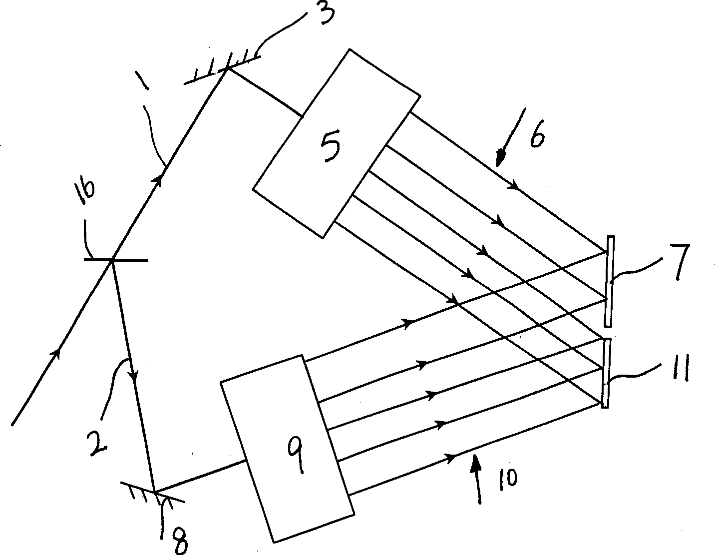
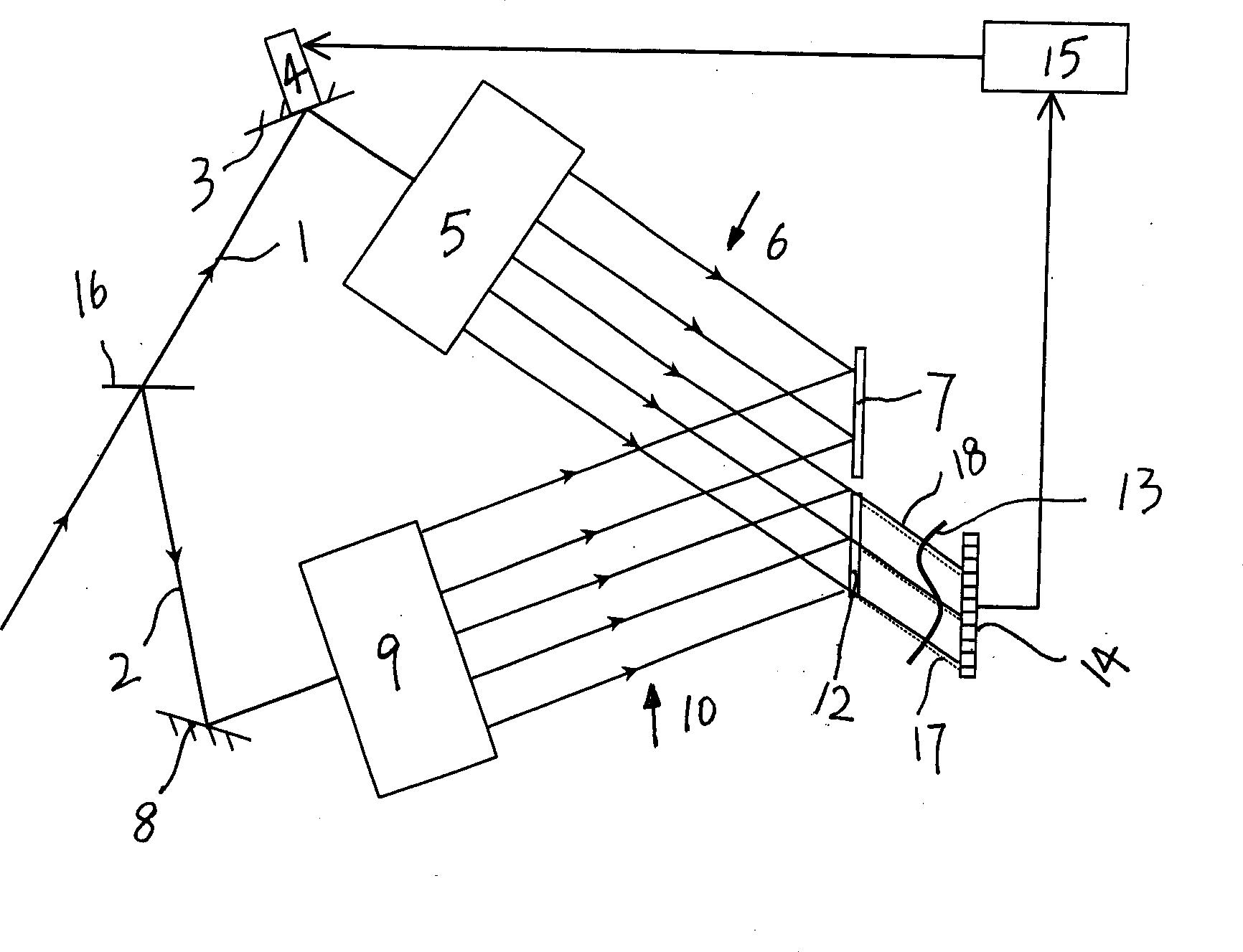
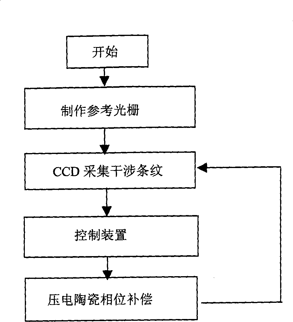
[0034] Such as figure 1 , figure 2 , image 3 A method for stabilizing holographic interference fringes with a control device is shown, which includes the following steps:

[0035] a. Divide the laser light into object light 1 and reference light 2 through the beam splitter 16, the object light 1 becomes the object wide beam 6 after passing through the object light reflector 3 and the object light beam expander system 5, and irradiates on the main recording dry plate 7 The reference light 2 becomes the reference wide beam 10 after passing through the reference light reflector 8 and the reference beam expander system 9, and also irradiates on the main recording stem plate 7; the object wide beam 6 and the reference wide beam 10 interfere with each other in the main recording stem Interference fringes are formed on version 7;

[0036] A reference dry plate 11 is also provided on the same plane as the main recording dry plate 7, and the object wide beam 6 and the reference wi...


PUM


Abstract

The invention relates to a method for using one controller to stabilizing the holographic interference pattern, and relative device. The external disturbance will cause the random excursion of holographic interference pattern, to reduce the quality of shot holographic grating. The invention uses linear CCD to collect the interference pattern information to the controller; the controller calculates the stripe excursion and control the piezoelectric ceramic that connected to the reflector to move and process phase compensation, to reduce the excursion of interference strip, and stabilize the interference strip in exposal area, therefore, the exposal time can be prolonged significantly.

Description

technical field [0001] The invention mainly relates to a method and device for stabilizing holographic interference fringes, in particular to a method and device for stabilizing holographic interference fringes with a control device. Background technique [0002] When shooting a large-scale holographic grating, a long exposure time is required due to the weak shooting light intensity. However, factors such as external vibration, air flow, and temperature fluctuations will change the relative phase of the object light and reference light, and the interference fringes formed by them will drift randomly, thereby reducing the contrast of the recorded fringes. Generally speaking, the fringe drift The amount should be less than 1 / 8 wavelength, otherwise it will easily cause the quality of the recorded holographic interference fringes to decrease, or even fail to record the interference fringes. None of the current holographic tables can guarantee that ...

Claims


Application Information

Patent Timeline
IPC IPC(8): G03H1/04G02B5/32
Inventor 李朝明吴建宏朱亚一居戬之胡祖元陈新荣刘全韦小茹
Owner SUZHOU UNIV
Why Eureka
Try Eureka