Suppression of undesirable signal propagation mode(s) downstream of a mode converter

A mode converter and propagation mode technology, applied in the field of optical transmission, can solve problems such as difficult production of optical fibers

A mode converter and propagation mode technology, applied in the field of optical transmission, can solve problems such as difficult production of optical fibers

CN1846158AInactive Publication Date: 2006-10-11DRAKA COMTEQ BV

Image

  • Suppression of undesirable signal propagation mode(s) downstream of a mode converter
  • Suppression of undesirable signal propagation mode(s) downstream of a mode converter
  • Suppression of undesirable signal propagation mode(s) downstream of a mode converter

Examples


Embodiment Construction

[0027] The invention relates to suppression of unwanted guided modes downstream of a mode converter.

[0028] For this purpose, an optical device for transforming the propagation mode of an optical signal is proposed, which device may for example be embedded in (or constitute) a dispersion compensation module embedded in an optical fiber transmission line.

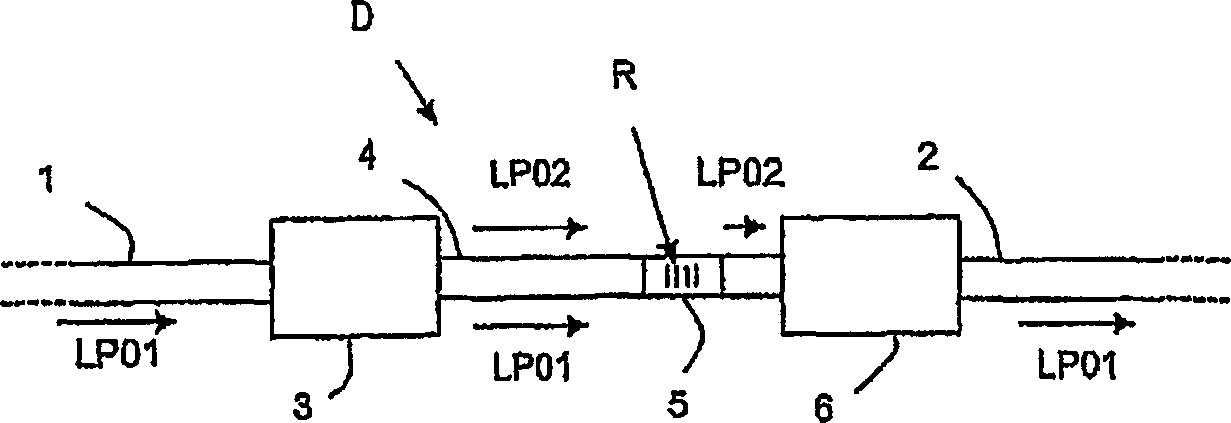
[0029] figure 1 The illustrated transmission line comprises an upstream optical fiber 1 connected to a downstream optical fiber 2 by means of a transmission device D according to the invention.

[0030] Similar to the downstream fiber 2, the upstream fiber 1 is for example a single mode fiber (SMF) in which a signal in a first guided mode, for example a fundamental LP01 mode, is propagated.

[0031] The illustrated conversion device D comprises a first mode converter 3 coupled to a multimode or multimode optical fiber (or also a HOM optical fiber) 4, wherein the optical fiber 4 is provided with a passive mode filter 5 and...


PUM


Abstract

An optical device (D) is dedicated to the transformation of the propagation mode of optical signals. This device comprises at least a first mode converter (3) that is supplied with signals that are propagated in a first guided mode and that delivers the signals in a multimode fibre (4) partly in the first guided mode and partly in a second guided more of a higher order that the first. The multimode fibre (4) comprises at least first passive filtering means (R) which have the task of converting the first guided mode into at least one dissipative cladding mode in order to prevent or limit the propagation of the signals in this first guided mode while at the same time authorising the propagation of the signals having the second guided mode in the multimode fibre (4).

Description

technical field [0001] The present invention relates to the field of optical transmission, and more particularly, to propagation mode conversion in optical transmission systems. Background technique [0002] Some waveguide structures, such as optical fibers, allow the transmission of optical signals in so-called "fundamental" propagation modes, or in so-called "higher-order" or higher-order propagation modes which can in particular improve the overall optical transmission performance. Specifically, the waveguide structure can be arranged so that it can have characteristics such as highly negative dispersion and high effective surface, especially, these characteristics enable it to be integrated in a dispersion compensation module (DCM, which includes a dispersion compensation fiber (DCF fiber) ))middle. This is especially the case for multimode or more-mode fibers, also known as higher order mode (HOM) fibers, the manufacture of which is currently well understood. [0003]...

Claims


Application Information

Patent Timeline
11 Oct 2006
Publication
CN1846158A
IPC
G02B6/14; G02B6/02; G02B6/34
CPC
G02B6/02095; G02B6/14
Inventors
卡洛斯·德巴罗斯; 利昂内尔·普罗沃