

Hydrochloride waste regenerating process for spray roasting
A technology of spray roasting method and hydrochloric acid waste liquid, applied in the direction of combustion method, combustion type, incinerator, etc., can solve the problems of surrounding workshops and environmental pollution, etc.
- Summary
- Abstract
- Description
- Claims
- Application Information
AI Technical Summary
Problems solved by technology
Method used
Image

Examples
Embodiment Construction
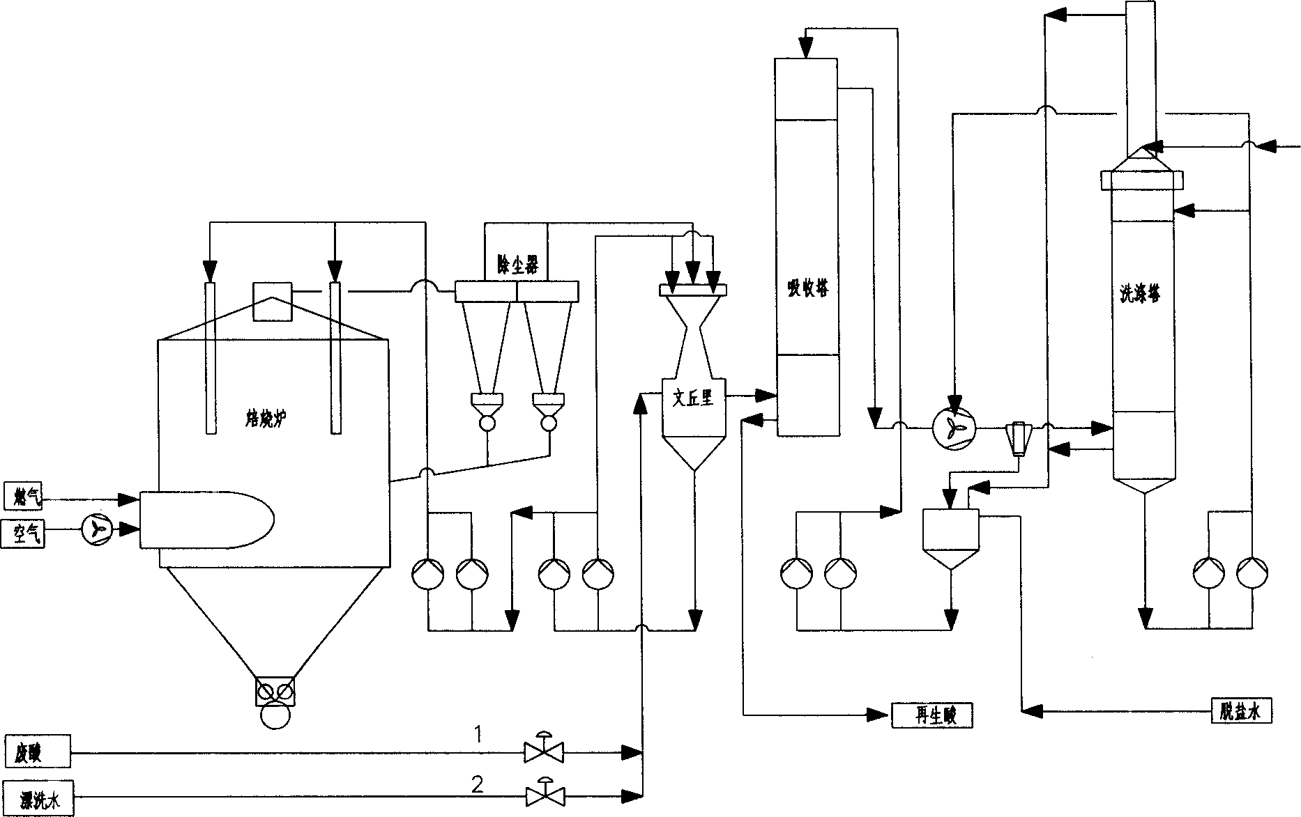
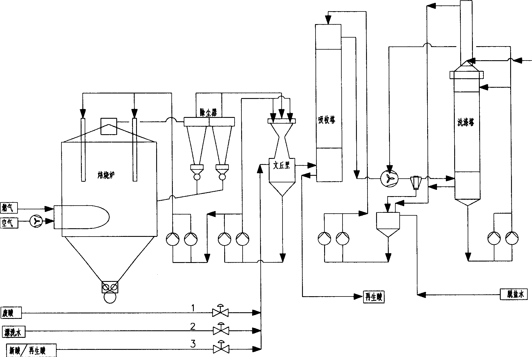
[0014] The present invention will be further described below in conjunction with the accompanying drawings.
[0015] Such as figure 2 Shown, spray roasting method hydrochloric acid waste liquor regeneration process, it comprises the following steps: 1), water operation: roasting furnace heats up, and after roasting furnace ignites and heats up to furnace top 390 ℃, carries out water operation, and rinsing water enters Venturi pre-concentrator , spray into the roaster through the roaster feed pump for water operation, the temperature, pressure, and flow in the roaster reach the set value and run stably for 8-12 hours; 2), 5-10 minutes before the acid operation, Stop supplying rinsing water to the Venturi pre-concentrator, supply hydrochloric acid (new hydrochloric acid or the regenerated acid of the acid regeneration system) in the Venturi pre-concentrator, and the hydrochloric acid addition is to make the weight concentration of hydrochloric acid in the Venturi pre-concentrat...
PUM
 Abstract
Description
Claims
Application Information