Steel twisted line tension test sensor

A technology of tension measurement and sensor, which is applied in the field of force measurement, can solve the problems that the size and distribution of the channel friction resistance cannot be detected, it cannot be judged whether the force of the steel strand is uniform, and the magnitude of the tension cannot be detected, etc., so as to achieve simple structure and easy use Long life, reasonable design effect

Inactive Publication Date: 2006-10-25
CHANGAN UNIV
View PDF0 Cites 5 Cited by
  • Summary
  • Abstract
  • Description
  • Claims
  • Application Information

AI Technical Summary

Problems solved by technology

The tensile force measured in this way is the resultant force of the whole bundle of steel strands, and the magnitude of the pulling force of each steel strand cannot be detected, so it cannot be judged whether the stress of each steel strand in the whole bundle of steel strands is even. As a result, one or several steel strands under a large force are broken during the tensioning process, thus leaving engineering hidden dangers
In addition, the size of the channel friction and its distribution alon

Method used


Image

  • Steel twisted line tension test sensor
  • Steel twisted line tension test sensor
  • Steel twisted line tension test sensor

Examples


Embodiment 1

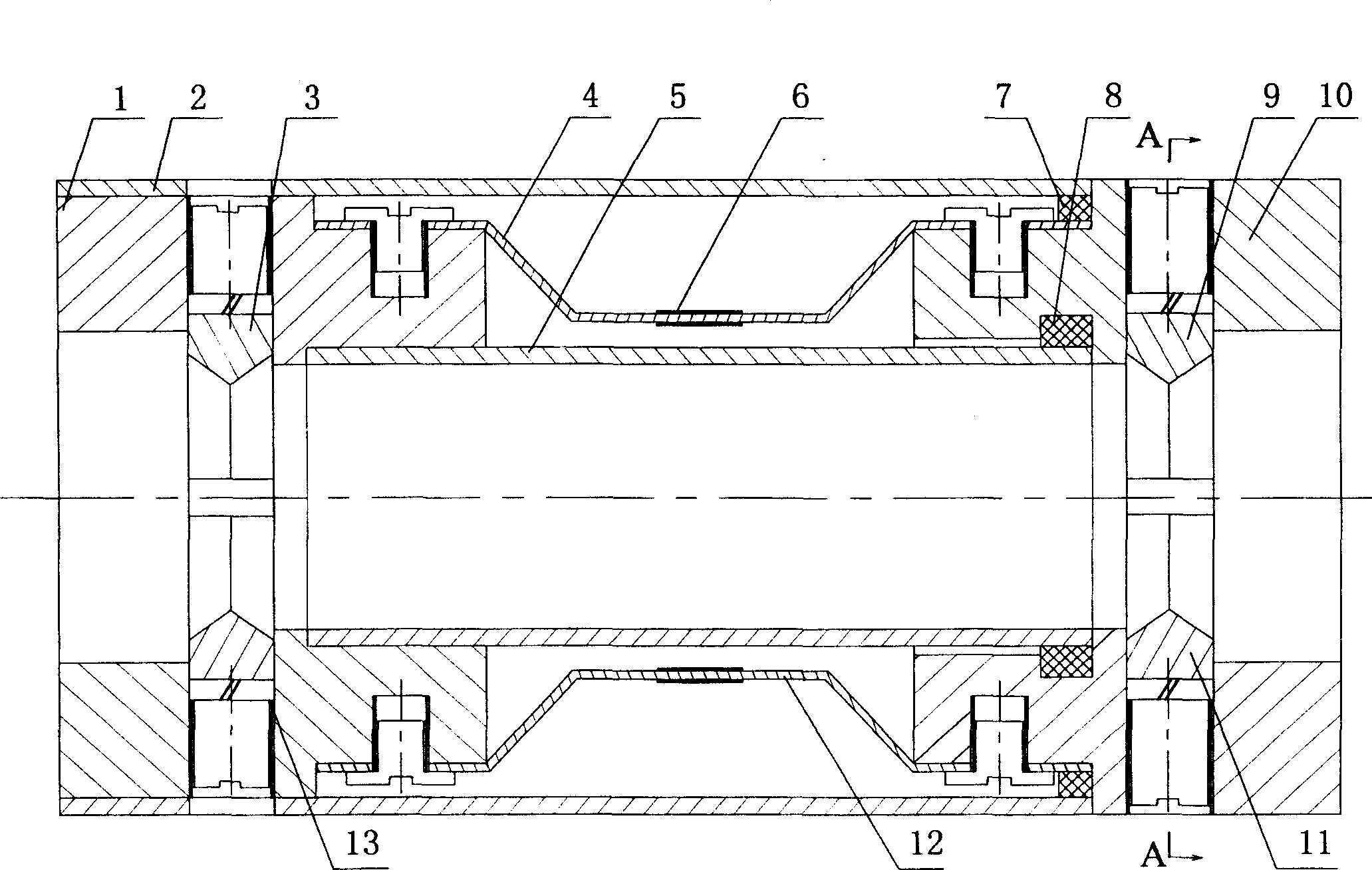
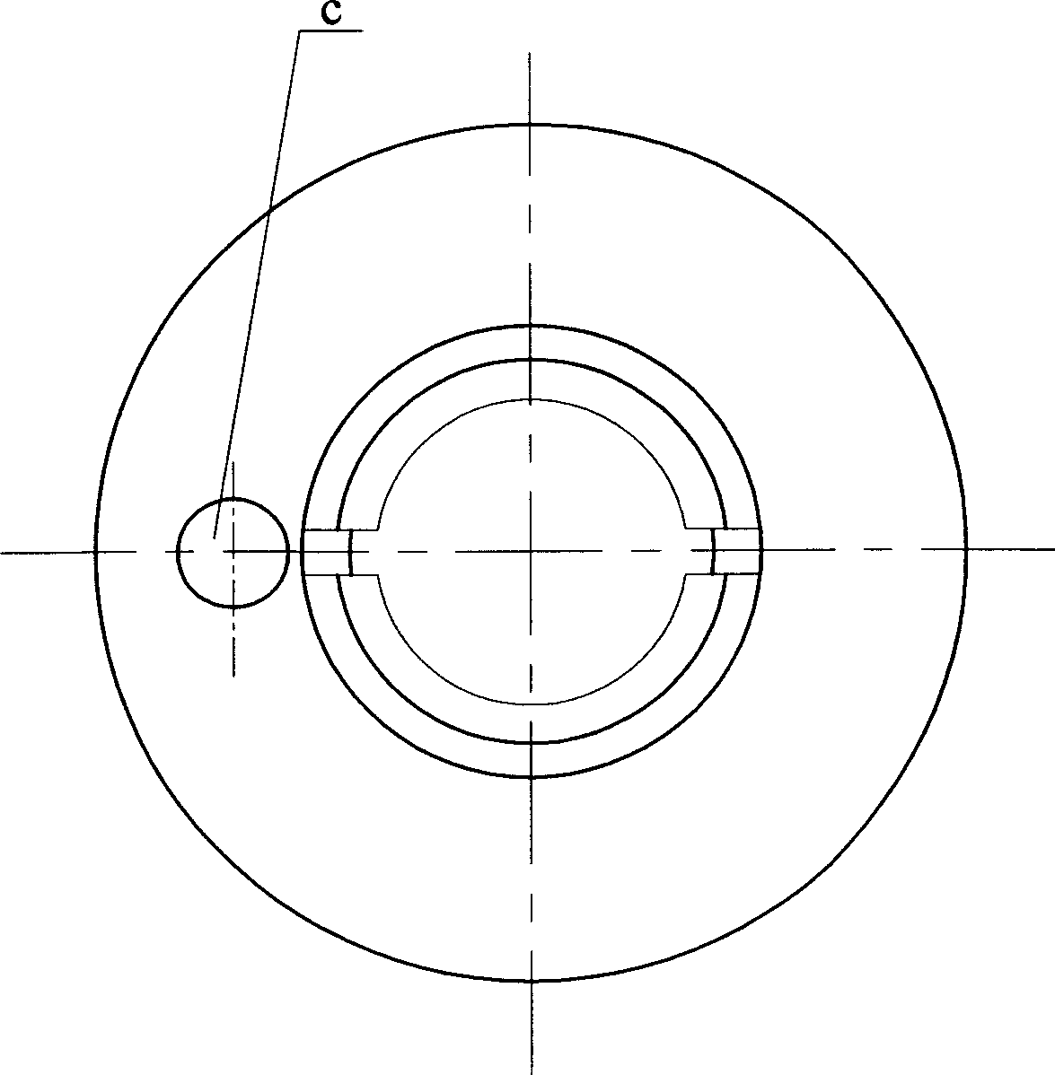
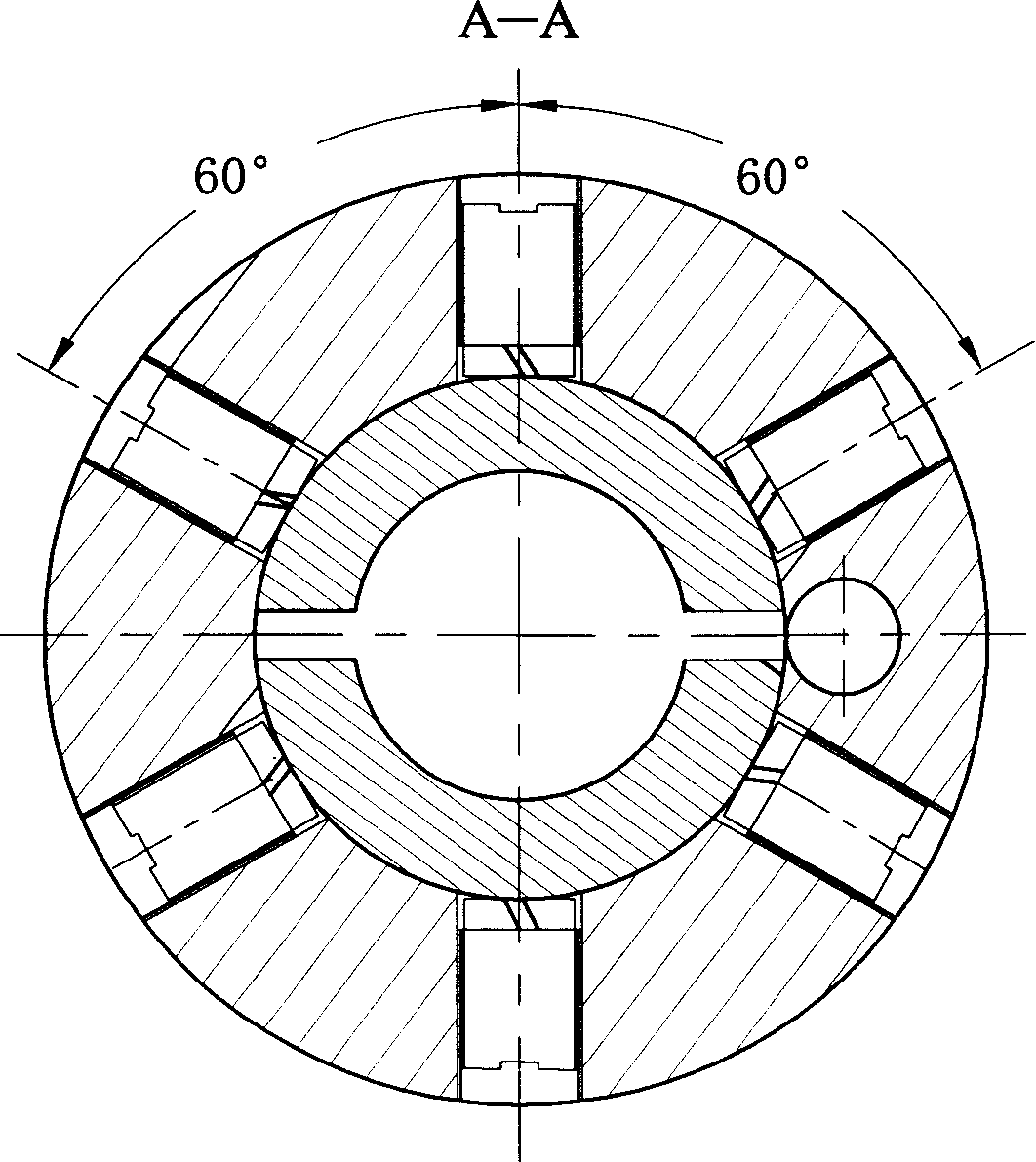
[0021] exist figure 1 , 2 , 3, 4, and 5, the steel strand tension measuring sensor of the present embodiment consists of the left end fixed sleeve 1, the outer casing 2, the upper left clamping wedge ring 3, the upper spring leaf 4, the inner casing 5, the strain gauge 6, Outer rubber ring 7, inner rubber ring 8, upper right clamping wedge ring 9, right end fixed cover 10, right lower clamping wedge ring 11, lower spring leaf 12, left lower clamping wedge ring 13 are connected to form.

[0022] The left end of the inner casing 5 is covered with a left end fixed sleeve 1, and the right end is covered with a right end fixed sleeve 10. An inner rubber ring 8 is installed between the inner casing 5 and the right end fixed sleeve 10, and the inner rubber ring 8 acts as a seal. A gap is left between the inner casing 5 and the right-end fixed sleeve 10 to allow relative movement between the inner casing 5 and the right-end fixed sleeve 10 . There are 6 screw holes uniformly distrib...

Embodiment 2

[0029]In this embodiment, the inner arc radius R of the upper left clamping wedge ring 3 and the lower left clamping wedge ring 13 is 2.5 mm, and the inner arc radius R of the upper right clamping wedge ring 9 and the lower right clamping wedge ring 11 is 2.5mm. The width b of the upper spring sheet 4 is 5 mm, the thickness t is 0.2 mm, the arc length L of the upper spring sheet 4 is 10 mm, the arc height h is 2 mm, and the angle α between the arc side and the bottom surface is 10°. The shape and structure of the lower spring leaf 12 are exactly the same as the upper spring leaf 4 . Other components and the coupling relationship of the components are the same as in Embodiment 1.

Embodiment 3

[0031] In this embodiment, the inner arc radius R of the upper left clamping wedge ring 3 and the lower left clamping wedge ring 13 is 7.6 mm, and the inner arc radius R of the upper right clamping wedge ring 9 and the lower right clamping wedge ring 11 is 7.6mm. The width b of the upper spring sheet 4 is 10 mm, the thickness t is 0.5 mm, the arc length L of the upper spring sheet 4 is 80 mm, the arc height h is 7 mm, and the angle α between the arc side and the bottom surface is 30°. The shape and structure of the lower spring leaf 12 are exactly the same as the upper spring leaf 4 . Other components and the coupling relationship of the components are the same as in Embodiment 1.


PUM

PropertyMeasurementUnit
Widthaaaaaaaaaa
Thicknessaaaaaaaaaa
Thicknessaaaaaaaaaa

Abstract

The invention relates to a steel twisted line tension measuring sensor that sets left end fixing cover on the left end of inner protecting canister, sets right fixing cover on the right end, sets inner gum ring between inner protecting canister and the right fixing cover. Left upper clipping wedge ring and left upper clipping wedge ring are set on the left end fixing cover. Right upper clipping wedge ring and right upper clipping wedge ring are set on the right end fixing cover. One end of the 2-8 even number spring tabs are set on the left end fixing cover and the other end is set on the right end fixing cover. Strain gauge is set on every spring tab. The strain gauge is connected by wire to form bridge circuit. The invention has reasonable design, simple structure, high accuracy, long useful file etc. It could be used to measure the tension of steel twisted line.

Description

technical field [0001] The invention belongs to the technical field of force measurement, and in particular relates to a steel strand tension measurement sensor. technical background [0002] Steel strand is made of high-quality carbon structural steel used in steel mills after cold processing, tempering and twisting. It has the advantages of good plasticity, no joints, convenient use, and high strength. It is currently widely used in various prestressed Concrete structure buildings, such as bridges, high-rise buildings, stadiums, industrial plants, mine storage and other buildings. [0003] During the construction of prestressed concrete structures, most of the component concrete is poured first, and holes (or casings) are reserved in it. After the concrete reaches the required strength, multiple (up to 37) steel strands are placed. The wire is inserted into the reserved channel, supported by the jack at the end of the concrete member, and the steel strand is stretched, so...

Claims


Application Information

Patent Timeline
IPC IPC(8): G01L5/04
Inventor 王建华胡大琳徐岳王春生白鹏翔王雪玲曹少飞李赞荣杨莹浩
Owner CHANGAN UNIV
Why Eureka
Try Eureka