Sheet brake for a press

A technology for brakes and printing presses, which is applied in the directions of sending objects, function instructions, thin material processing, etc., to achieve the effect of high efficiency and enhanced rhythm operation.

Active Publication Date: 2006-11-01
HEIDELBERGER DRUCKMASHINEN AG
View PDF3 Cites 2 Cited by
  • Summary
  • Abstract
  • Description
  • Claims
  • Application Information

AI Technical Summary

Problems solved by technology

However, the effectiveness of the late

Method used


Image

  • Sheet brake for a press
  • Sheet brake for a press
  • Sheet brake for a press

Examples


Embodiment Construction

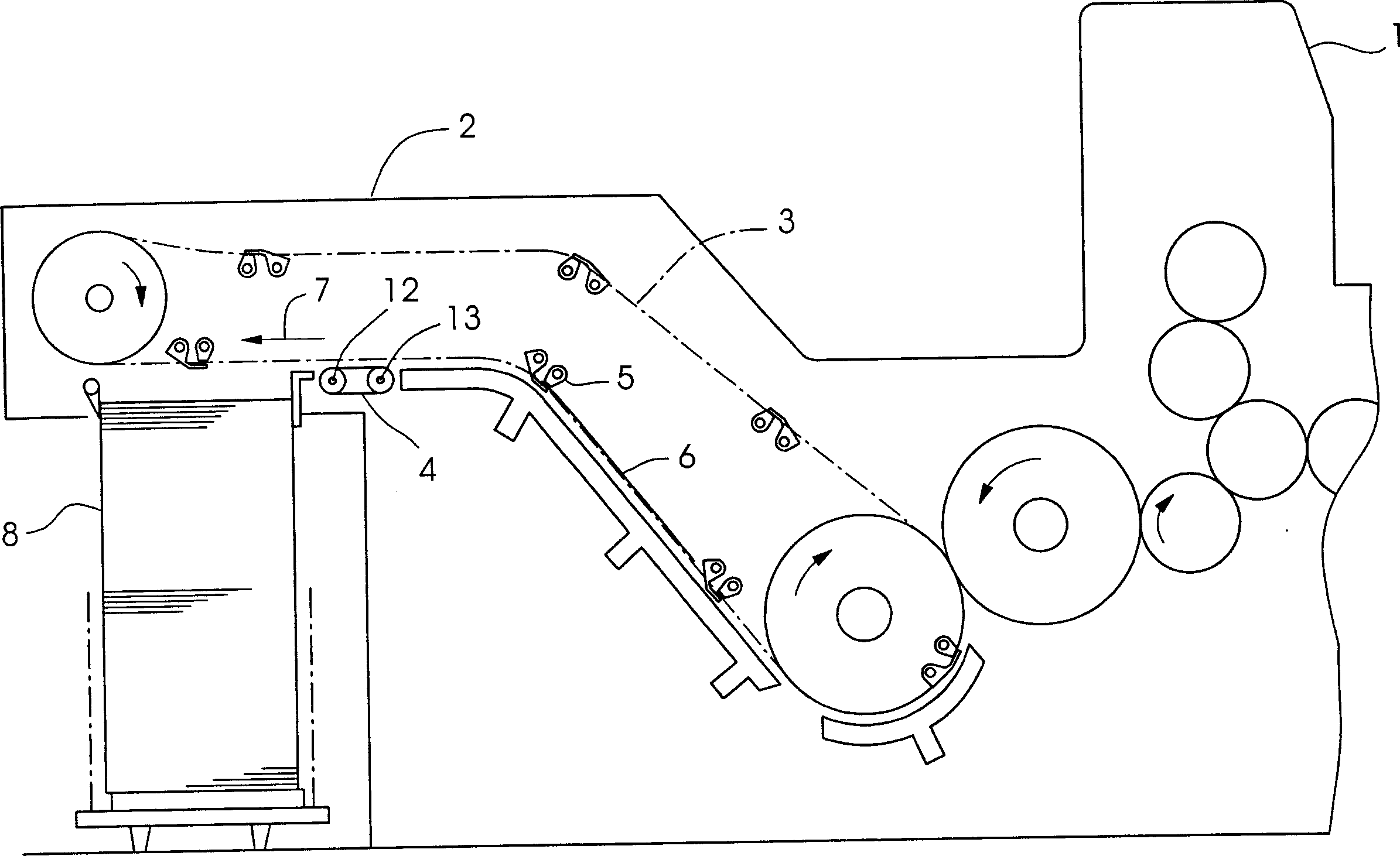
[0018] figure 1 A printing press 1 for perfecting printing is shown. The printing press 1 comprises a delivery 2 with a chain conveyor 3 and a sheet brake 4 arranged below the chain conveyor 3 . The chain conveyor 3 has gripper bridges 5 for securely gripping the leading edge of the printing material sheet 6 . Before the printed product sheet 6 is deposited on the delivery pile 8 , the sheet brake 4 brakes the printed product sheet 6 and in this case tensions the printed product sheet 6 transversely to the sheet travel direction 7 .

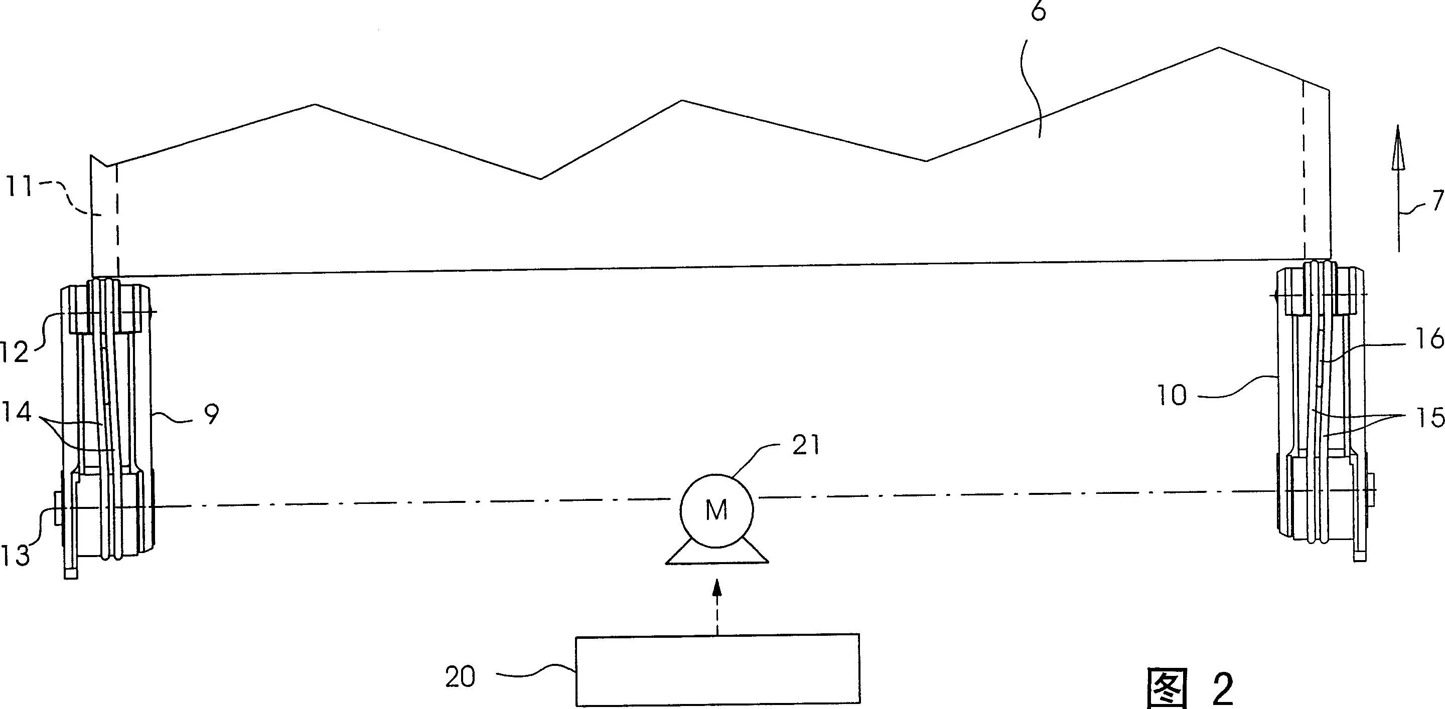
[0019] FIG. 2 shows that the sheet brake 4 only includes a first brake assembly 9 and a second brake assembly 10 and does not include other brake assemblies. During braking and lateral tensioning, the first braking assembly 9 is in contact with a side edge 11 of the substrate sheet 6 without printed images, while the second braking assembly 10 is in contact with the other side edge. Between the two brake assemblies 9 , 10 the printing materia...


PUM


Abstract

The invention relates to a sheet brake of a printing press, comprising braking bodies (14, 15) diverging in the sheet travel direction (7) for lateral tensioning of a printing material sheet (6). The braking bodies (14, 15) are driven in a circular motion at a non-uniform speed (VB).

Description

technical field [0001] The invention relates to a sheet brake of a printing machine, which has a braking body diverging in the running direction of the sheet, and is used for lateral tensioning of the sheet of the substrate. Background technique [0002] DE 39 39 212 A1 describes a sheet brake whose brake body is designed as a suction ring. The suction rings are oriented divergently, that is to say from the center of the machine opposite to each other obliquely outwards, so that the printing material sheet is drawn obliquely outward on both sides by the suction rings and tensioned transversely to the direction of sheet travel. However, the effectiveness of this transverse tension still needs to be improved. [0003] DE 44 35 988 A1 and DE 196 20 938 A1 contain other prior art. Contents of the invention [0004] The object of the present invention is to provide a sheet brake which can be effectively tensioned transversely. [0005] This object is solved by a sheet brake....

Claims


Application Information

Patent Timeline
IPC IPC(8): B65H29/68
CPCB65H29/686B65H2301/51242B65H2406/32B65H2513/10B65H2557/242B65H2801/21B65H2220/09B65H2220/02B65H2220/11
Inventor 安德烈亚斯·伯特格尔米夏埃多·迪瓦斯斯文·利帕德特斯特凡·迈尔阿尔贝特·毛尔弗兰克·施拉姆马尔特·塞德勒
Owner HEIDELBERGER DRUCKMASHINEN AG
Why Eureka
Try Eureka