Memory disposition methods and systems

A configuration system and configuration method technology, applied to memory systems, instruments, program control devices, etc., can solve problems such as memory capacity limitations and inability to modify at will, and achieve the effect of reducing costs

Active Publication Date: 2006-11-01
MEDIATEK INC
View PDF0 Cites 2 Cited by
  • Summary
  • Abstract
  • Description
  • Claims
  • Application Information

AI Technical Summary

Problems solved by technology

However, when all software programs are stored in the read-only memory, some defects in the software programs cannot be modified arbitrarily.
In addition, memory capacity in most embedded systems is limited

Method used


Image

  • Memory disposition methods and systems
  • Memory disposition methods and systems
  • Memory disposition methods and systems

Examples


Embodiment

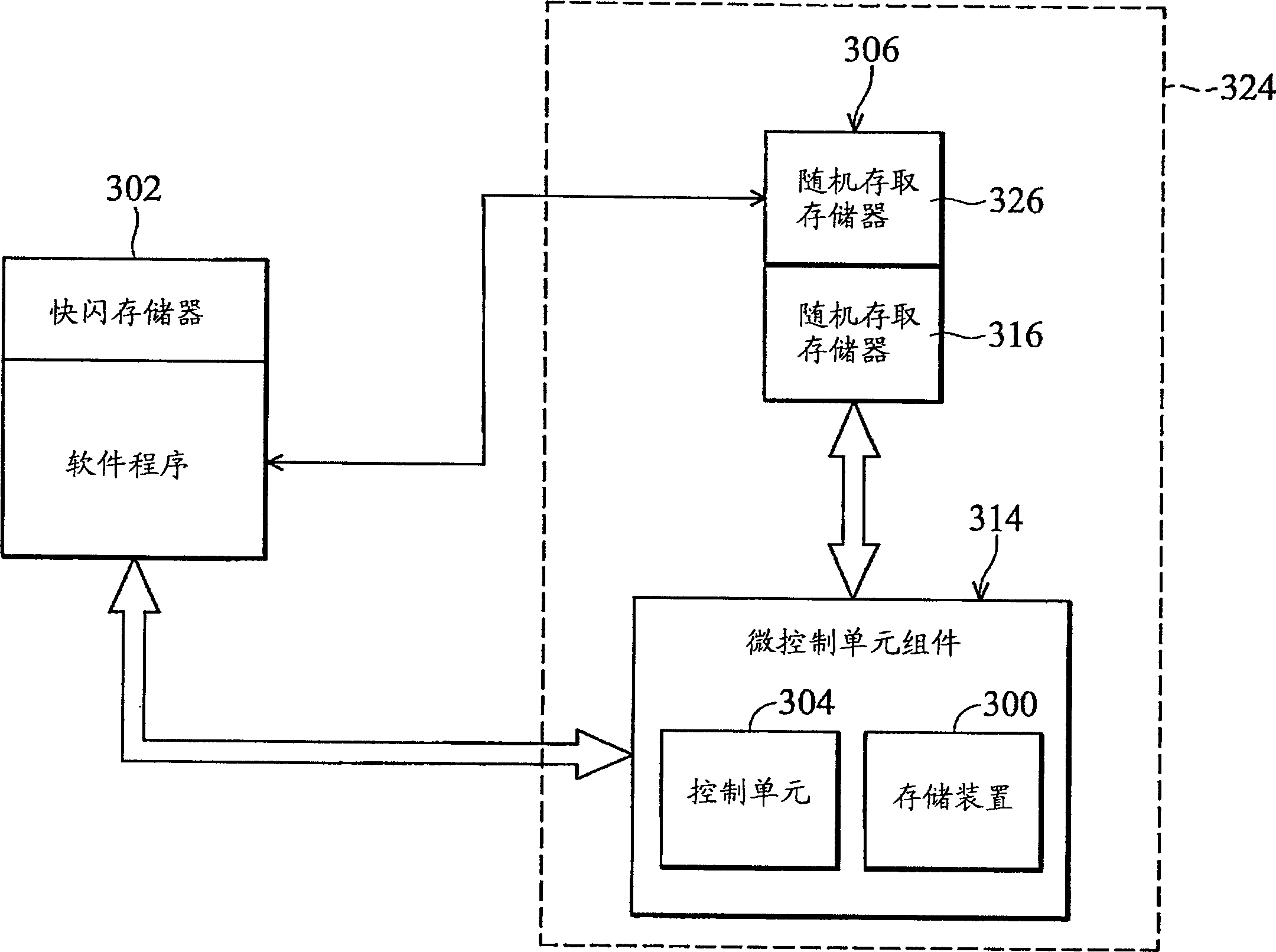
[0022] image 3 is a schematic diagram showing a memory configuration system according to an embodiment of the present invention. The storage configuration system includes a first storage device 300 and a second storage device 302 . The first storage device 300 and the second storage device 302 are coupled to the control unit 304 of the system. The control unit 304 may be a micro control unit (micro control unit, MCU).

[0023] The first storage device 300 stores a first program controlled by the control unit 304 . The first storage device 300 may be a one-time programmable memory device, such as a read-only memory (ROM). The second storage device 302 stores a second program related to the first program controlled by the control unit 304 . The relationship between the first program and the second program includes data reference and function call. A function table is stored in a fixed address of the second storage device 302 for data reference and function calling. The se...


PUM


Abstract

A memory disposition system, comprising a first memory device and a second memory device. First and second memory devices are provided to a system, such as an embedded system. The first and the second memory devices are coupled to a control unit, such as micro control unit. The first memory device stores first programs and the second memory device second programs. The first and second programs are controlled by the control unit. The first memory device can be a one time programmable memory device, such as a ROM, and the second memory device a multiple times programmable memory device, such as a flash memory.

Description

technical field [0001] The present invention relates to a system control method, in particular to a memory configuration method and system suitable for a system with a control unit. Background technique [0002] An embedded system usually includes a combination of fixed or programmable hardware and software. Embedded systems are usually designed for specific application devices, such as mobile phones and personal digital assistants (PDAs). Therefore, the components of an embedded system are different from those of a general computer system. For example, due to hardware limitations of the application device (such as a mobile phone), the storage device disposed in the embedded system of the application device may be designed to have a limited capacity. [0003] In general, an embedded system usually has a control unit, such as a micro control unit (MCU), for performing system control, and a storage device, such as a flash memory, for storing programs. The software program i...

Claims


Application Information

Patent Timeline
Patent Type & Authority Applications(China)
IPC IPC(8): G06F9/445
CPCG06F12/0638
Inventor 许嘉容黄致铨林彦璋
Owner MEDIATEK INC
Why Eureka
Try Eureka