Connector

A connector and housing technology, applied in the field of connectors, can solve the problems of loss of durability of conductive terminals, damage of contact durability, and poor operability, and achieve reduced deflection, stable closed state, and good operability. Effect

Inactive Publication Date: 2006-11-01
JST MFG CO LTD
View PDF2 Cites 2 Cited by
  • Summary
  • Abstract
  • Description
  • Claims
  • Application Information

AI Technical Summary

Problems solved by technology

[0009] However, in the connector disclosed in Patent Document 1, the pressing piece of the contact is elastically deformed, and the pressing piece of the contact is pressed against the FPC in conjunction with the elastic deformation of the pressing piece. Deformation stress always acts on the point, and there are disadvantages such as creep phenomenon and impairing the durability of the contact
[0010] In addition, in the connector disclosed in Patent Document 2, the engaging portion of the cover is engaged with the engaging portion constituted by the "lever" type arm connected to the rear side of the conductive terminal (contact), and the cover Can be turned so that each time the cover is opened and closed, a load acts on the "lever" arm connected to the rear side of the conductive terminal (contact) to the detriment of the durability of the conductive terminal (contact)
And because the cover is not engaged with the housing, there are disadvantages such as easy disengagement of the engagement and poor operability.

Method used


Image

  • Connector
  • Connector
  • Connector

Examples


Embodiment Construction

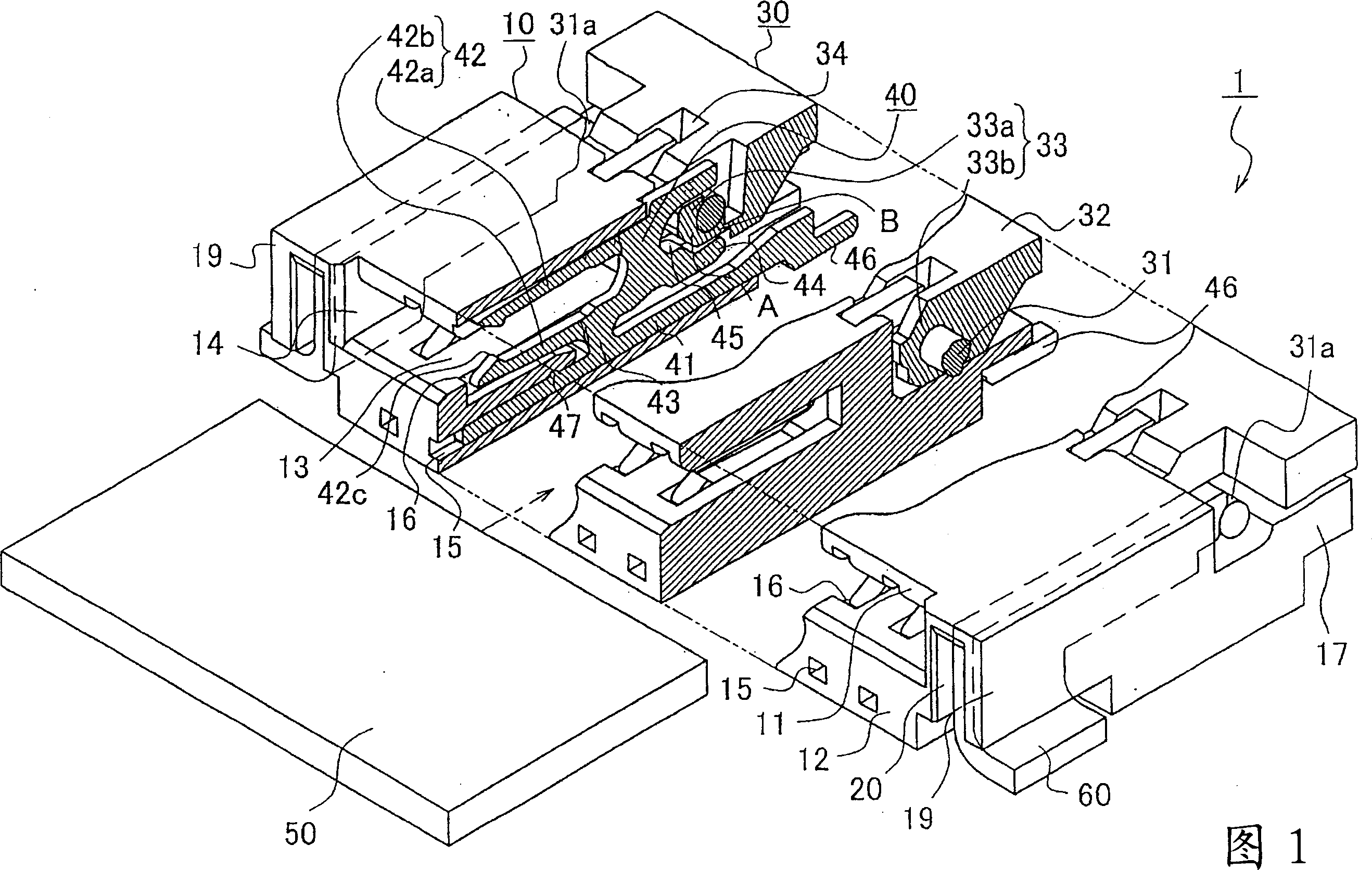
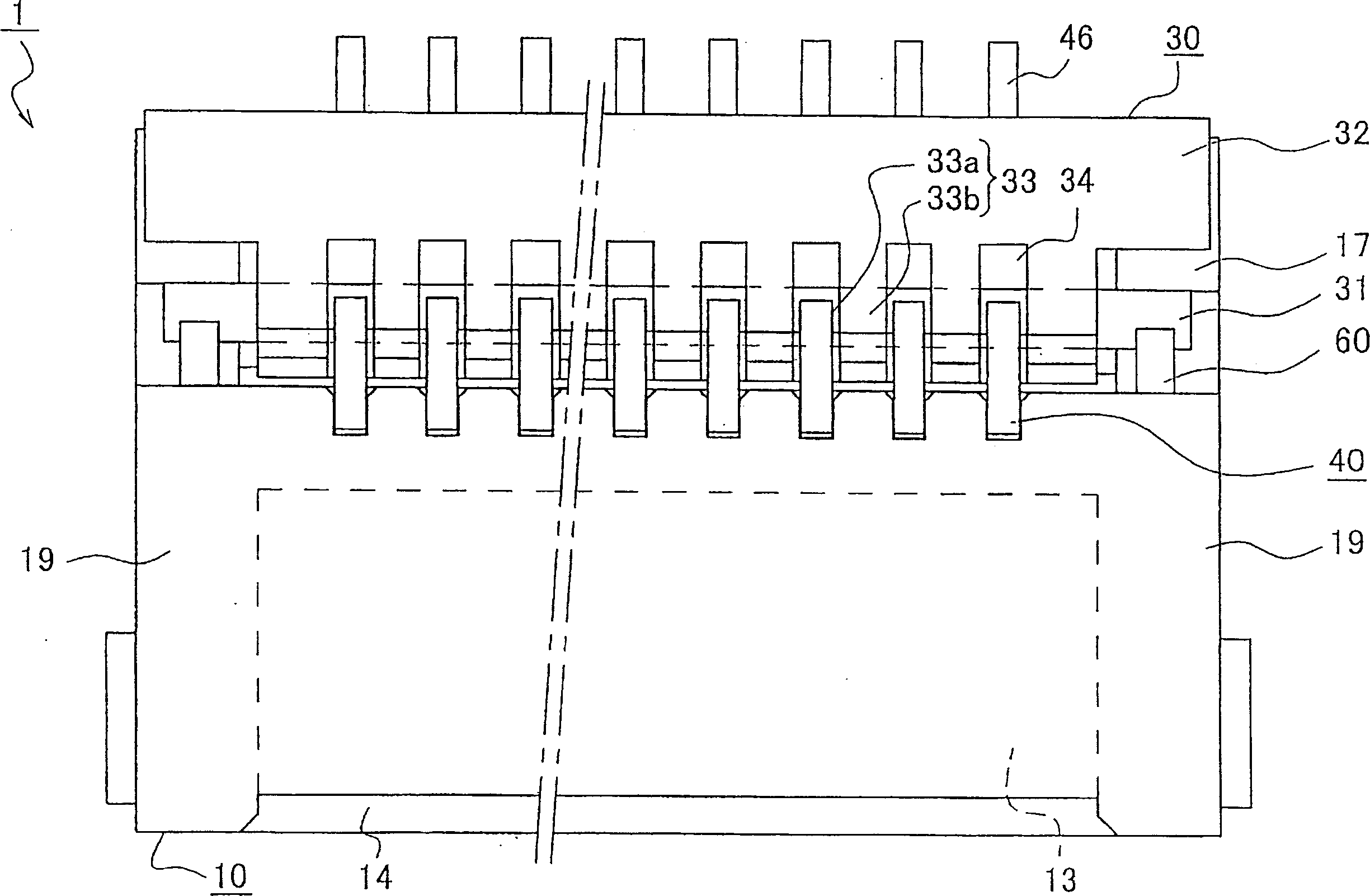
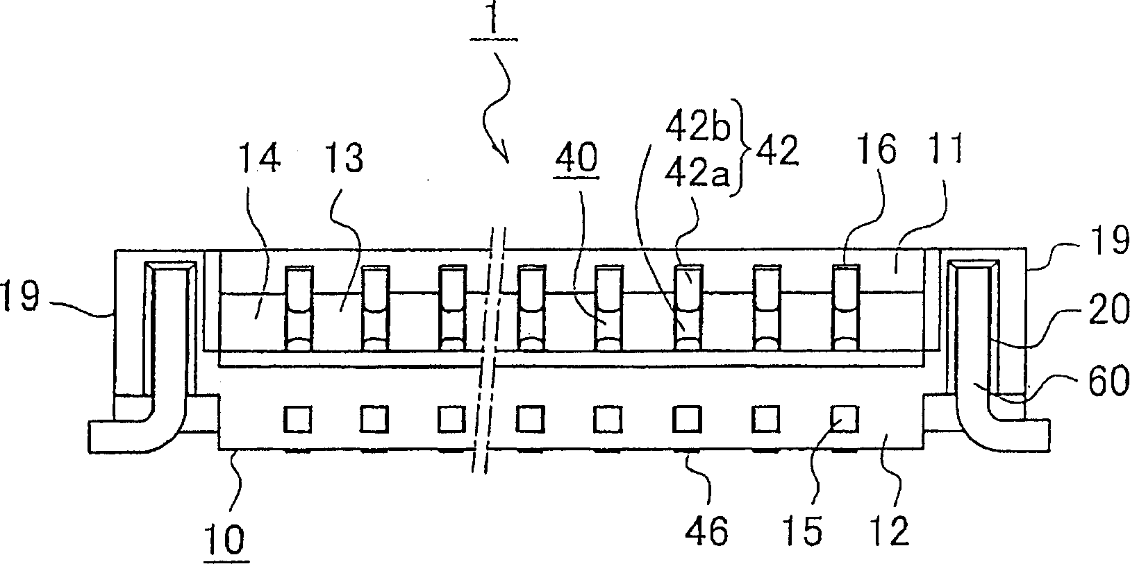
[0057] Hereinafter, specific embodiments of the present invention will be described with reference to the drawings.

[0058] FIG. 1 is a perspective view showing the structure of a connector according to an embodiment of the present invention, showing main parts in cross section. figure 2 is a plan view of the connector of the present invention. image 3 is a front view of the connector of the present invention. Figure 4 is a side view of the connector of the present invention. Fig. 5 is a perspective view of the connector according to the embodiment of the present invention, showing a state before FPC is connected with a part of the connector cut away. Image 6 It is a longitudinal sectional view of FIG. 5 . Fig. 7 is a perspective view of the connector according to the embodiment of the present invention, showing a state in which an FPC is connected with a part of the connector cut away. Fig. 8 is a longitudinal sectional view of Fig. 7 . In addition, in the above figu...


PUM


Abstract

A connector having a substantially box-like housing having an insertion opening into which an FPC is inserted, a two-forked contact placed inside the housing, and a lever provided so as to face the insertion opening of the housing and pivotably held by the housing. The two-forked contact has a base section held by the housing, an upper arm and a lower arm that extend from the base section toward the insertion opening, and two-forked engagement arms extending from the base section in the opposite direction to the insertion opening. The lever has a grip section, a rotating shaft provided on the grip section and held by the housing, and a first plate cam provided on the rotating shaft and engaging the engaging arm. When the grip section is opened, the first plate cam widens the interval between the two-forked engagement arms, widening the interval between the upper arm and the lower arm of the two-forked contact.

Description

technical field [0001] The present invention relates to a connector connected to a flat flexible cable such as FPC (Flexible Printed Circuit) or FFC (Flexible Flat Cable: Flexible Flat Cable). In particular, it relates to a connector that requires little force when inserting a flat flexible cable such as FPC or FFC. Background technique [0002] A plurality of terminals are arranged in parallel on the FPC, and when such an FPC is detachably connected to a printed circuit board, a connector in which a plurality of contacts are arranged in parallel is used. In the existing connectors, as described in Patent Document 1 or Patent Document 2, etc., the operating member presses the contact and the terminal of the FPC to perform crimping (compression), so that multiple terminals are connected together, and the FPC is kept from falling off. . [0003] In the connector disclosed in Patent Document 1, an FPC insertion port for inserting an FPC is formed on one side of the case, and ...

Claims


Application Information

Patent Timeline
Patent Type & Authority Applications(China)
IPC IPC(8): H01R12/79H01R12/88H01R24/00H01R107/00
CPCH01R12/79H01R12/88
Inventor 横山浩祐
Owner JST MFG CO LTD
Why Eureka
Try Eureka