Back light, light guiding plate, method for manufacturing diffusion plate and light guiding plate, and liquid crystal display device

A technology of liquid crystal display device and light guide plate, which can be used in lighting and heating equipment, light guide, diffusing elements, etc., and can solve problems such as ripples and display glare.

Inactive Publication Date: 2006-11-08
SONY CORP
View PDF2 Cites 9 Cited by
  • Summary
  • Abstract
  • Description
  • Claims
  • Application Information

AI Technical Summary

Problems solved by technology

[0007] However, by using a lens film to increase display brightness, moire may appear on the display screen due to interference between the liquid crystal display device and the lens film
Additionally, the display may exhibit a rippled glare when viewed at an angle

Method used


Image

  • Back light, light guiding plate, method for manufacturing diffusion plate and light guiding plate, and liquid crystal display device
  • Back light, light guiding plate, method for manufacturing diffusion plate and light guiding plate, and liquid crystal display device
  • Back light, light guiding plate, method for manufacturing diffusion plate and light guiding plate, and liquid crystal display device

Examples


Embodiment 1

[0112] A first embodiment of the present invention will be described with reference to the drawings.

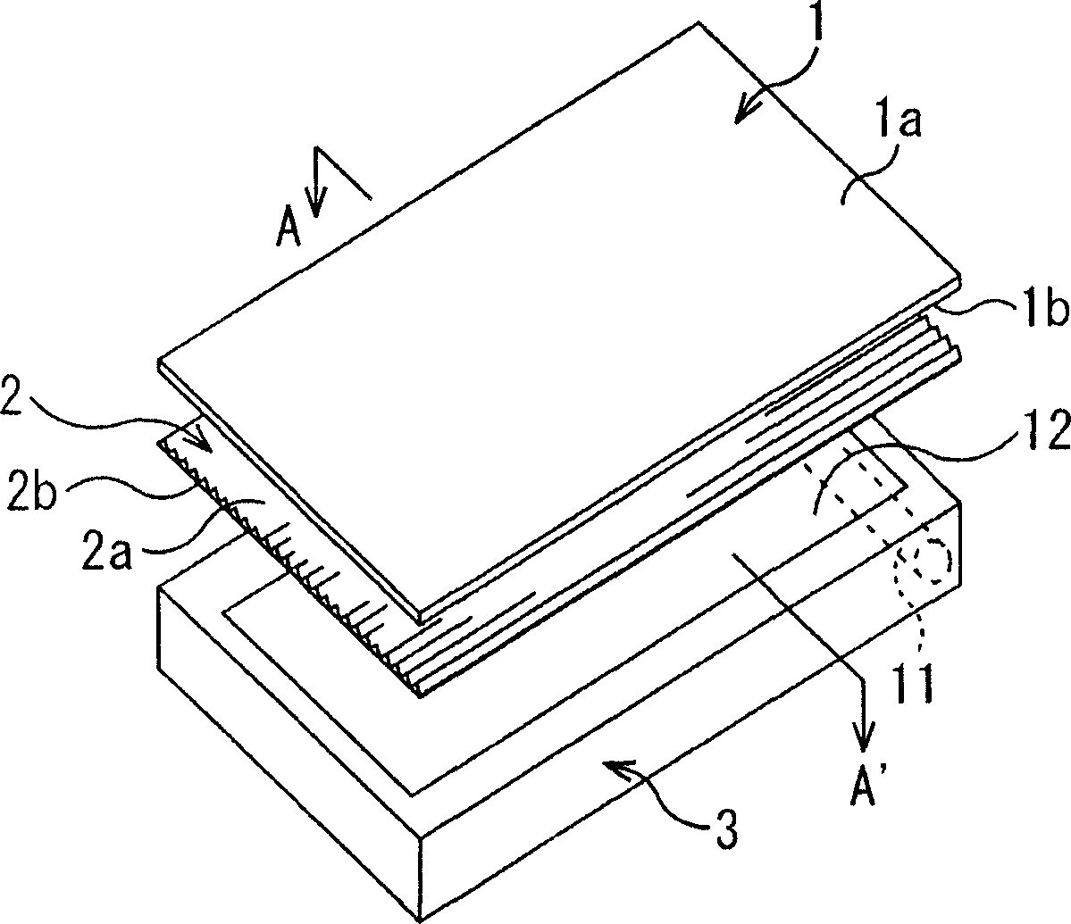
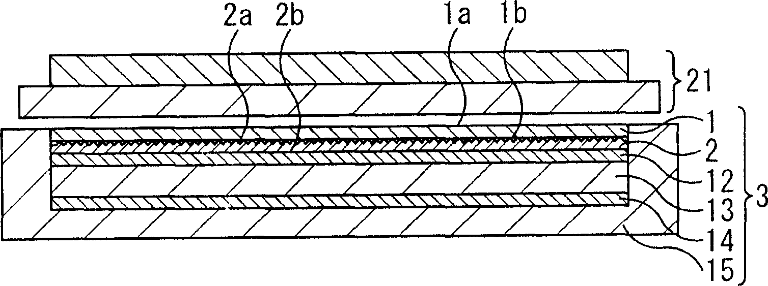
[0113] The type of backlight is a type in which, for example, cold cathode fluorescent lamps (CCFL) or light emitting diodes (LEDs) are arranged along and close to the side of a light guide plate formed of transparent synthetic resin for guiding light, and in which, for example, a plurality of cold cathode fluorescent lamps A type in which light sources are arranged parallel to each other. In the former, a diffuser is inserted between the light guide plate and the liquid crystal display device, and in the latter, a diffuser is inserted between a plurality of cold cathode fluorescent lamps and the liquid crystal display device, and the diffuser is used to diffuse light to Irradiate evenly onto the LCD display.

[0114] In Embodiment 1, a description will be given of a case where light sources such as a plurality of cold cathode fluorescent lamps are arranged in parallel with ...

Embodiment 2

[0184] The best example of implementing the light guide plate according to the present invention and the method of manufacturing the light guide plate and the backlight will be described in detail below with reference to the accompanying drawings.

[0185] Similar to the case of Embodiment 1 described above, the type of backlight is a type in which, for example, cold cathode fluorescent lamps (CCFL) or light emitting diodes (LEDs) are arranged along and close to the side of a light guide plate formed of transparent synthetic resin for guiding light, and A type in which light sources such as a plurality of cold cathode fluorescent lamps are arranged in parallel to each other immediately below a liquid crystal display. In Embodiment 2, a case where a light source such as a light emitting diode is arranged along and close to a side surface of a light guide plate formed of a transparent synthetic resin for guiding light will be described.

[0186] exist Figure 22 A light guide p...


PUM


Abstract

The present invention relates to a backlight and a light guide plate, a method of manufacturing a diffuser and the light guide plate, and to a liquid crystal display apparatus, all enabling a cost reduction by reducing the parts count and curtailing unnecessary manufacturing processing. A diffuser 261 has a light distribution layer 181 including a prismatic surface wherein stripe grooves or asperities are arrayed in parallel with each other, a diffusion layer 182 containing diffusion elements 191 for diffusing incident light, and a light incidence control layer 271 including a prismatic surface wherein stripe grooves or asperities are arrayed in parallel on a side of fluorescent tubes 131 . The diffusion layer 182 is formed from the same resin, and only the diffusion elements 191 are formed from a different resin. The prism of the light incidence control layer 271 is optimized so as to enhance the proportion, to light being reflected without entering the light incidence control layer 271 , of light re-entering other parts of a surface of the light incidence control layer 271 , in order to guide incident light toward the diffusion layer 182 efficiently. The present invention is applicable to a backlight of a liquid crystal display apparatus.

Description

technical field [0001] The invention relates to a preparation method of a backlight and a light guide plate, a diffusion plate and a light guide plate, and a liquid crystal display device. In particular, the present invention relates to a manufacturing method of a backlight and a light guide plate, a diffuser and a light guide plate, and a liquid crystal display device, all of which can reduce costs by reducing the number of parts and reducing unnecessary manufacturing processes. Background technique [0002] Liquid crystal display devices include: a liquid crystal display device (also referred to as an LCD panel) in which two transparent glass substrates are aligned and superimposed on each other so that their surfaces face each other, and these surfaces include transparent electrodes, alignment films, etc. laminated thereon , and wherein liquid crystal is sealed between two substrates; a backlight, disposed under the liquid crystal display device, for supplying light to th...

Claims


Application Information

Patent Timeline
Patent Type & Authority Applications(China)
IPC IPC(8): G02B5/02G02F1/1335F21S2/00F21Y103/00G02B6/00G02F1/13357
Inventor 奥贵司畠中正斗川岛良成越村章白鸟和洋
Owner SONY CORP
Why Eureka
Try Eureka