Pen with propulsive refill

A telescopic, refill technology, applied to ink pens, pen holders, ball-point pens, etc. with an ink storage tube in the pen holder, can solve the problems of difficulty in meeting consumers' demands for innovation and changes, different operation methods, and inability to interoperate, etc. Conducive to large-scale production, prolong use time, and improve the effect of competitiveness

Inactive Publication Date: 2006-11-15
马益民
View PDF2 Cites 14 Cited by
  • Summary
  • Abstract
  • Description
  • Claims
  • Application Information

AI Technical Summary

Problems solved by technology

The structures of the above-mentioned known push-type pens and swing-type pens are different from each other

Method used


Image

  • Pen with propulsive refill
  • Pen with propulsive refill
  • Pen with propulsive refill

Examples


Example Embodiment

[0019] The present invention will be further described in detail below in conjunction with the accompanying drawings and embodiments.

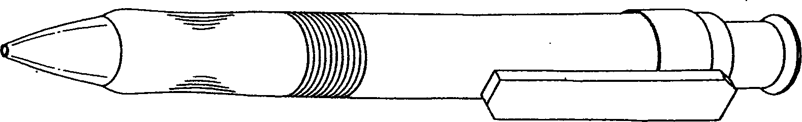
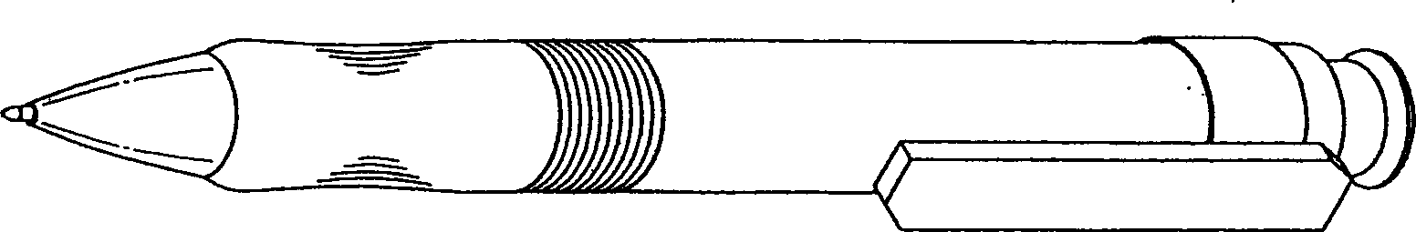
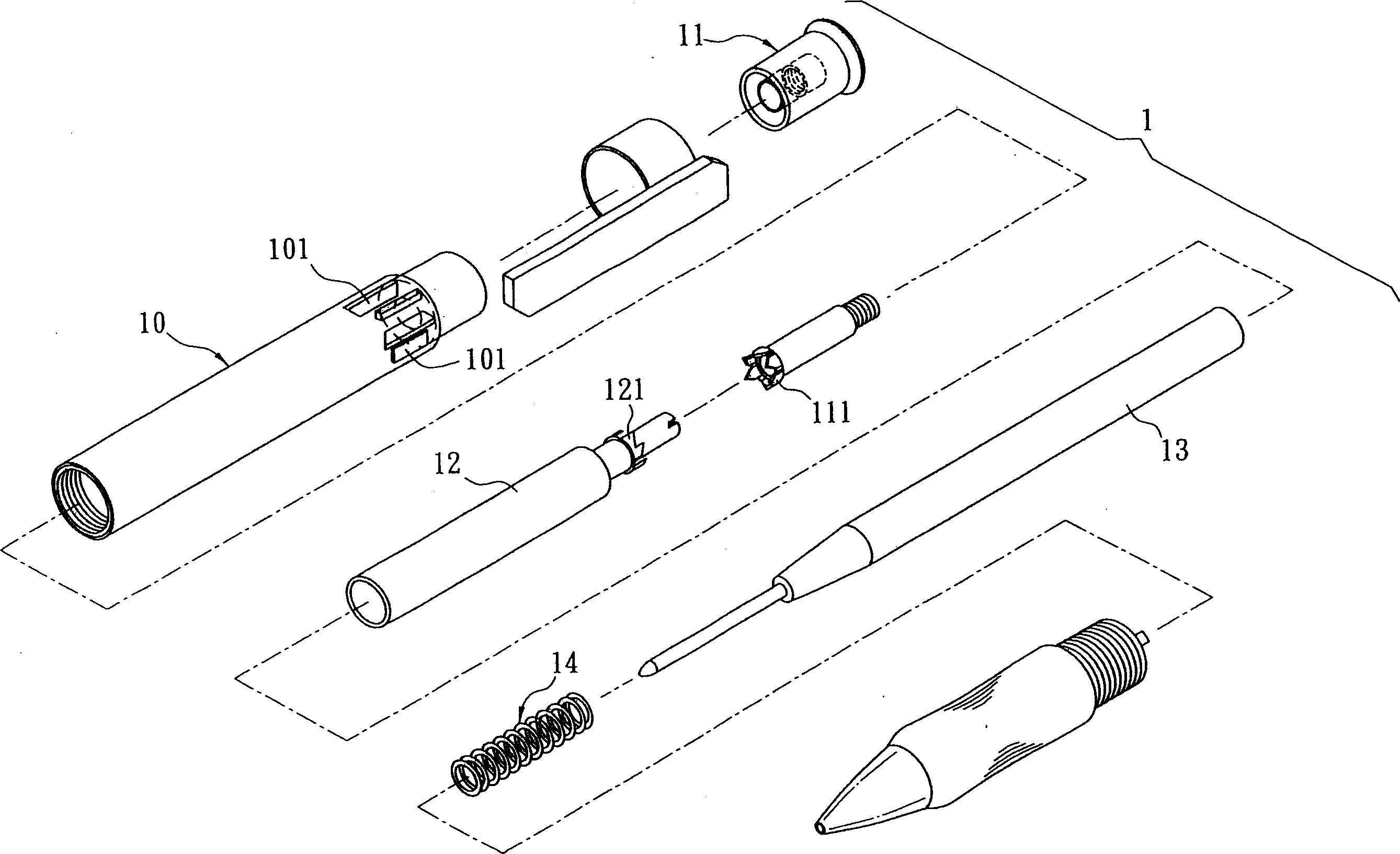
[0020] Referring to Figures 5 to 8, the retractable pen 2 of the present invention is similar in appearance to the general push-type pen 1, but the known general push-type pen 1 can only press the button to control the expansion and contraction of the refill, while the present invention In addition to pressing the button to control the expansion and contraction of the pen core, the push-type pen 2 can also be swung forward to control the expansion and contraction of the pen core. This embodiment specifically includes an outer pen tube 20, a button 30, an inner sleeve 40, and The inner pen core 50 and the return spring 60 of the casing 40, the outer pen tube 20 is screwed to a front tube 23, and the outer pen tube 20 is provided with a central hole 22, and the inside of the tail end of the outer pen tube 20 is provided with several rings arrange...


PUM


Abstract

A pen with telescopic core features that its internal sleeve tube the first and the second stop rings respectively on its front and back ends, a load-bearing ring can slide on the internal sleeve tube between said two stop rings, and an axle rod passing through the internal flange at the front end of a hollow tube is connected with a sleeve ring via spiral threads.

Description

technical field [0001] The invention relates to an office writing tool, in particular to a pen with a retractable pen core. Background technique [0002] In the design field of writing pens, there are many different designs for the structure used to operate the expansion and contraction of the pen core. Among them, the most common one is a commonly called push-type pen, and its specific structure is as follows: Figures 1 to 4 As shown, the push-type pen 1 generally includes an outer pen tube 10 with several guide rails 101 inside the tail end, a button 11 with a ring-shaped ratchet 111 at the front end, an inner sleeve 12 with a ring-shaped ratchet 121 at the rear end, A set of pen core 13 in the inner casing 12 and a set of back-moving spring 14 on the front end of the pen core 13; figure 1 When the button 11 is pressed as shown, the annular ratchet 111 at the front end of the button 11 can slide linearly forward along several corresponding guide rails 101 of the outer pe...

Claims


Application Information

Patent Timeline
IPC IPC(8): B43K24/02B43K3/04B43K5/16B43K7/12B43K8/24B43K24/08
Inventor 马益民
Owner 马益民
Why Eureka
Try Eureka