Lamb wave type high frequency device
A Lamb wave, high frequency technology, applied in the field of Lamb wave type high-frequency devices, can solve the problems of frequency band fluctuation, abnormal oscillation, frequency jump, etc., to achieve the effect of reducing the number, suppressing the excitation, and enhancing the excitation
- Summary
- Abstract
- Description
- Claims
- Application Information
AI Technical Summary
Problems solved by technology
Method used
Image
Examples
Embodiment approach 1
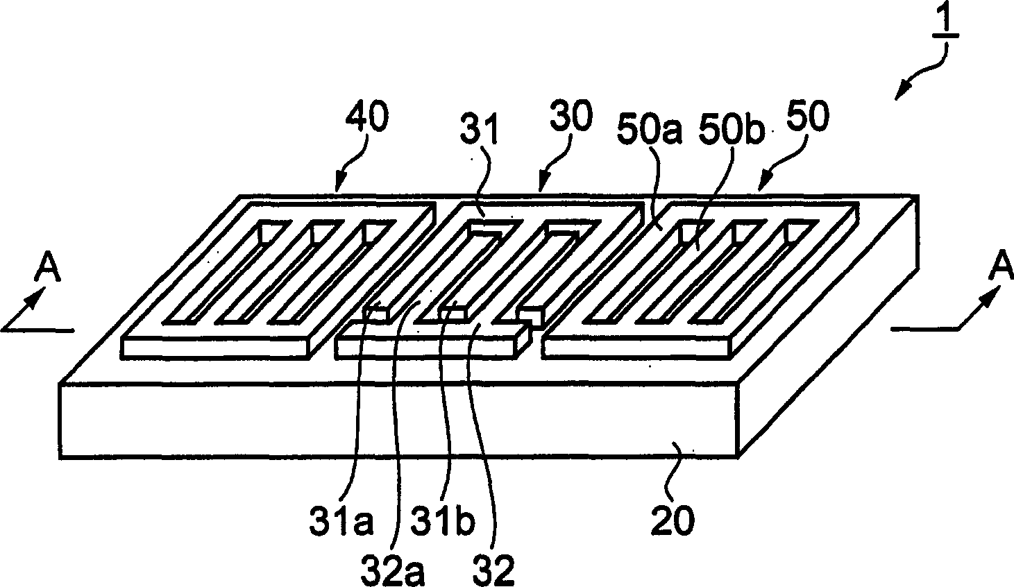
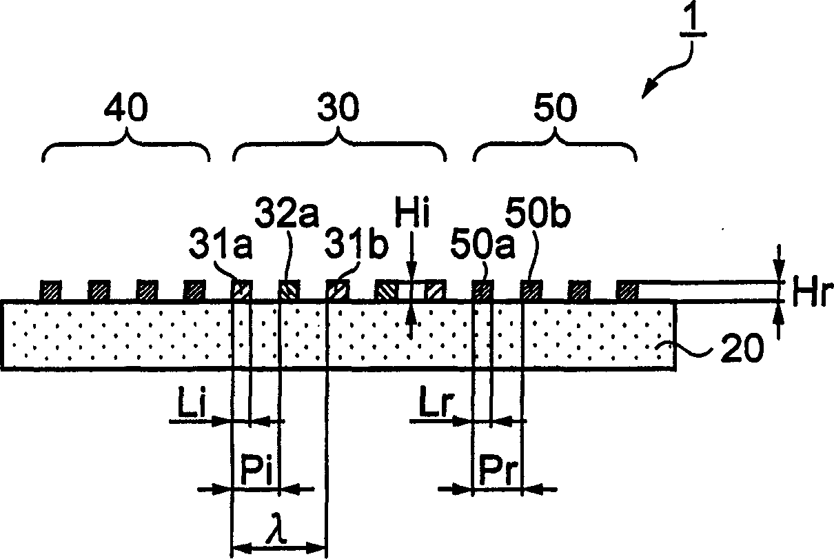
[0151] figure 1 is a perspective view showing the Lamb wave type high-frequency resonator 1 of Embodiment 1, figure 2 yes means figure 1 A cross-sectional view of the A-A section in .
[0152] exist figure 1 , figure 2 Among them, the Lamb wave type high-frequency resonator 1 is composed of an IDT electrode 30 having a pair of interdigitated electrodes 31, 32 on the surface of a piezoelectric substrate 20 made of quartz, and a pair of reflectors 40 having electrode fingers 50a, 50b. , 50 components. These reflectors 40 and 50 are provided on both sides in the traveling direction of the Lamb wave excited by the IDT electrode 30 . Hereinafter, one interdigital electrode 31 will be referred to as a first interdigital electrode 31 , and the other interdigital electrode 32 will be referred to as a second interdigital electrode 32 .
[0153] The first interdigital electrodes 31 and the second interdigital electrodes 32 of the IDT electrodes 30 are formed so as to be inter...
Embodiment approach 2
[0166] Next, a Lamb wave type high-frequency resonator according to Embodiment 2 of the present invention will be described with reference to the drawings. Embodiment 2 is the same as the aforementioned Embodiment 1 (refer to figure 1 , 2 ), the structure of the electrode fingers of the IDT electrode is different, which is characterized in that the electrode fingers of the 4 IDT electrodes are inserted alternately within the range of the wavelength λ of the Lamb wave.
[0167] Figure 6 , 7 The structure of the Lamb wave type high-frequency resonator of Embodiment 2 is shown, Figure 6 is its stereogram, Figure 7 yes means Figure 6 Sectional view of the B-B section in . exist Figure 6 , 7 Among them, the Lamb wave type high-frequency resonator 2 is composed of an IDT electrode 30 formed on the surface of a piezoelectric substrate 20 made of quartz, and reflectors 40 and 50 provided at both ends thereof. Its basic configuration is the same as that of Embodiment 1. ...
Embodiment approach 3
[0178] Next, a Lamb wave type high-frequency resonator according to Embodiment 3 of the present invention will be described with reference to the drawings. The feature of this embodiment is that an insulating film covering the upper surface of the IDT electrode 30 described in Embodiments 1 and 2 is formed, and the structures of the IDT electrode 30 and reflectors 40 and 50 may be the same as those of Embodiments 1 and 2. Structure. Here, based on Embodiment 1 (refer to figure 1 , 2 ), assign the same symbols to the same parts, and only explain the different parts.
[0179] Figure 9 , 10 The Lamb wave type high-frequency resonator 3 of Embodiment 3 is shown, Figure 9 is its stereogram, Figure 10 yes means Figure 9 Sectional view of the C-C section in . exist Figure 9 , 10 In this case, an insulating film 60 covering the entire IDT electrode 30 is formed on the surface of the IDT electrode 30 . The insulating film 60 is made of SiO 2 form.
[0180] In additio...
PUM
 Abstract
Description
Claims
Application Information
 - R&D
- Intellectual Property
- Life Sciences
- Materials
- Tech Scout
- Unparalleled Data Quality
- Higher Quality Content
- 60% Fewer Hallucinations
Browse by: Latest US Patents, China's latest patents, Technical Efficacy Thesaurus, Application Domain, Technology Topic, Popular Technical Reports.
© 2025 PatSnap. All rights reserved.Legal|Privacy policy|Modern Slavery Act Transparency Statement|Sitemap|About US| Contact US: help@patsnap.com


