Tapered roller bearing and method of machining tapered roller

A tapered roller bearing, tapered roller technology, applied in the direction of roller bearings, rolling contact bearings, bearings, etc., can solve problems such as cost increase, uneven contact surface roughness, and roller damage.

Active Publication Date: 2006-11-15
NTN CORP
View PDF0 Cites 24 Cited by
  • Summary
  • Abstract
  • Description
  • Claims
  • Application Information

AI Technical Summary

Problems solved by technology

[0010] For example, making a roller having a convex surface with a size larger than a specified size will cause the roughness of the contact surface of the roller to be uneven, which makes the roller easy to be damaged on this surface (see Japanese Unexamined Patent Publication 2003-172360)
In addition, reducing the roughness of the entire surface of the roller to have 0.4 μm or less at irregular ten-point heights (0.08 μm or less on the centerline average roughness) would result in a significant cost increase
Even split rollers have similar cost issues

Method used


Image

  • Tapered roller bearing and method of machining tapered roller
  • Tapered roller bearing and method of machining tapered roller
  • Tapered roller bearing and method of machining tapered roller

Examples


Embodiment Construction

[0024] Embodiments of the present invention will be described below with reference to the drawings.

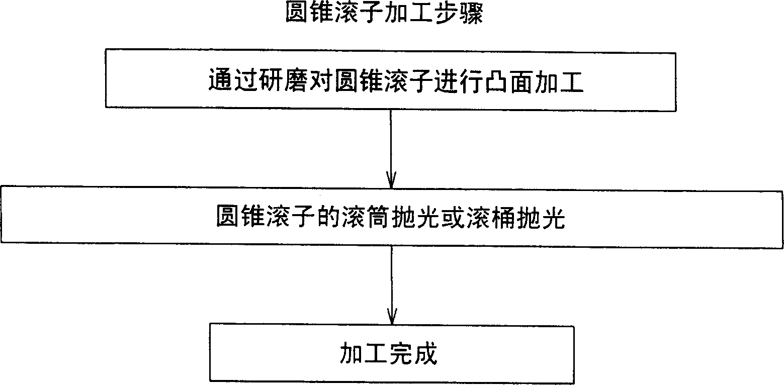
[0025] figure 1 A method for machining the rollers in the tapered roller bearing of the invention is shown. First, the tapered rollers are crowned by grinding. Next, barrel polishing or barrel polishing is continued on the crowned tapered roller surface until the grinding streaks disappear.

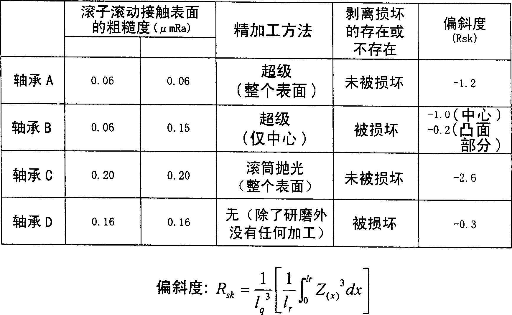
[0026] Tapered roller bearings were assembled using the above machined rollers, and the bearings were tested for peel damage. figure 2 Shown are the results of an experiment comparing bearing C related to the present invention with bearings A, B, and D tested as comparative examples under the same conditions. Each roller of bearings A to D has the same crown formed by grinding.

[0027] Bearing A has a roller with the entire convex surface finished by super machining. The roughness of the entire surface thereof is good, but high cost is required to process the bearing. In bearing ...


PUM


Abstract

The invention discloses a method for machining the tapered roller of a tapered roller bearing, which is characterized in that a roller is subjected to crowning machining by grinding and then is subjected to fine machining by barrel polishing or tumbler polishing so as to remove grinding marks. Due to the adoption of the method, each tapered roller is crowning-processed by grinding and finished by barrel polishing or tumbler polishing so as to be provided with a large crowning, while the tapered roller is low in cost and deflection-resistant. Meanwhile, the super-processing operation, which causes peeling damage on the raceway surface and shortens the service life of the roller, is no longer adopted.

Description

technical field [0001] The present invention relates to a tapered roller bearing suitable for supporting, for example, automotive transmission rod sections under significant misalignment and a method for machining the tapered rollers thereof. Background technique [0002] image 3 An example of a tapered roller bearing used in a typical manual transmission rod section is shown. The bearing has tapered rollers 3 held by a cage 4 and placed between an inner ring 1 and an outer ring 2 . The inner ring 2 has a conical raceway surface 1a, and is provided with a large collar surface 1b on the large diameter side. The outer ring 2 is not a separate component, rather the inner surface of the bearing constitutes the outer ring 2 . Due to the structural constraints of the drive, the bearings used for this part cannot be designed with a thicker section height H. However, since it is placed in a heavy-load environment, it must have a large load capacity, so the tapered roller bearing...

Claims


Application Information

Patent Timeline
Patent Type & Authority Applications(China)
IPC IPC(8): B23F19/00B24B5/04B24B1/00B24B31/00F16C19/36F16C33/36
CPCB24B1/00B24B31/00F16C19/364F16C33/36F16C2240/50F16C2240/54
Inventor 辻本崇
Owner NTN CORP
Why Eureka
Try Eureka