Seatbelt retractor and seatbelt device equipped with the seatbelt retractor

A seat belt retractor and seat belt technology, which is applied to the structure of seat belts/slings, in-vehicle seat belts, belt tensioners, etc., can solve the problem that the force transmission part 13 is difficult to return, engage and disengage, and limit the load. It can not be uniform and other problems to achieve the effect of reducing the drop of seat belt load, reliable torsional deformation, and absorbing impact energy

Inactive Publication Date: 2006-11-22
TAKATA CORPORATION
View PDF2 Cites 4 Cited by
  • Summary
  • Abstract
  • Description
  • Claims
  • Application Information

AI Technical Summary

Problems solved by technology

[0027] However, in the seat belt retractor 1 having the pretensioner 11 and the torsion bar 7 of the EA mechanism as described above, after the seat belt retraction is completed by the operation of the pretensioner 11, When the seat belt is pulled out due to the inertia of the occupant, if there is gas remaining in the pipe 12, under the influence of the residual pressure of the gas, each force transmission member 13 is difficult to return, and in the metal-to-metal clutch mechanism, the internal teeth 19 and The engagement of the external teeth 21 is difficult to disengage
Therefore, it is difficult for the spool 4 to rotate in the direction in which the seat belt is pulled out, such as Figure 12 As shown by the dotted line in , the dynamic characteristics of the seat belt retractor 1 (seat belt load-occupant (chest) movement amount characteristic) in the EA region where the torsion bar 7 performs EA action, there is a locally large limit load Several peaks that are prominent to a certain extent (two peaks A and B in the example in the illustration) and several large load drops (one drop C in the example in the illustration), the limit load cannot be uniform

Method used


Image

  • Seatbelt retractor and seatbelt device equipped with the seatbelt retractor
  • Seatbelt retractor and seatbelt device equipped with the seatbelt retractor
  • Seatbelt retractor and seatbelt device equipped with the seatbelt retractor

Examples


Embodiment Construction

[0051] Preferred modes for implementing the present invention will be described below with reference to the drawings.

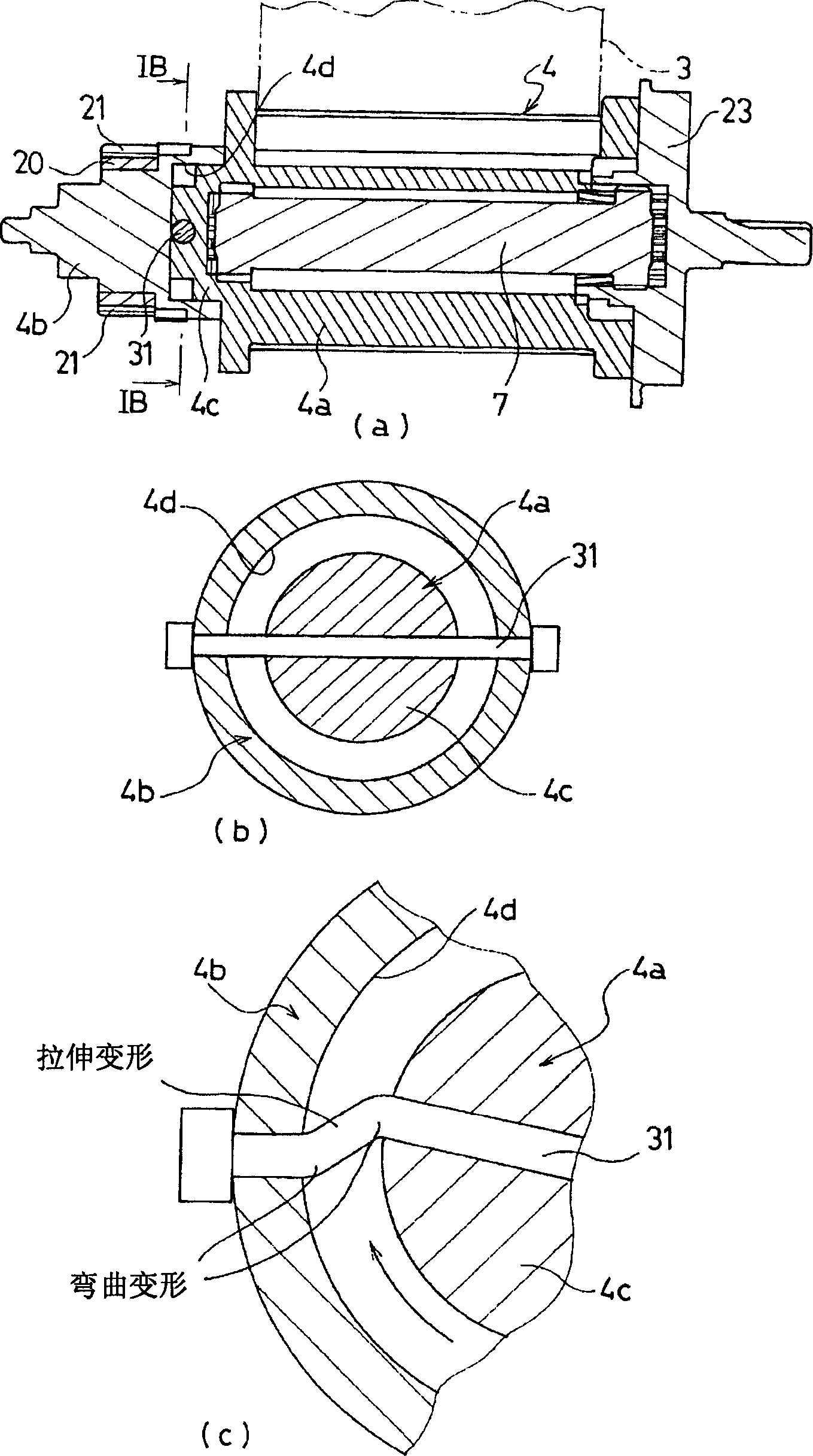
[0052] figure 1 Partially and schematically showing an example of an embodiment of the seat belt retractor according to the present invention, (a) shows a sectional view of the spool of this example, and (b) is taken along the line IB-IB in (a) (c) is a partial enlarged view for explaining the behavior of the pretensioner after operation. And in the description of each embodiment below, for the example before this example and the above Figure 10 (a), (b) and Figure 11 The same constituent elements in the shown conventional example are denoted by the same symbols, and detailed description thereof will be omitted.

[0053] in the above Figure 10 (a), (b) and Figure 11 In the shown conventional example, the spool 4 is integrally constituted by a single part with the belt winding portion of the seat belt 3 and the fixing portion of the pinion 20 of the cl...


PUM


Abstract

In order to efficiently and sufficiently achieve an EA function by an EA mechanism when a seatbelt (3) is being withdrawn due to an inertia force from a vehicle occupant after a belt-retracting operation performed by a pretensioner (11) when the seatbelt (3) is being withdrawn due to an inertia force from a vehicle occupant after a belt-retracting operation by the pretensioner (11), a relative rotational torque is generated between a first spool component (4a) retracting the seatbelt (3) and a second spool component (4b) to which a driving force of the pretensioner (11) is transmitted. When the relative rotational torque reaches a predetermined value or more, a pin (31) is subject to bending deformation and tensile deformation so that the first spool component (4a) rotates relatively with respect to the second spool component (4b) in a belt-withdrawing direction. Accordingly, a spool (4) rotates in a belt-retracting direction so that a torsion bar (7) becomes twisted, whereby impact energy is absorbed.

Description

technical field [0001] The invention relates to a seat belt device equipped in a vehicle such as a motor vehicle. In an emergency situation such as when a large deceleration acts on the vehicle when the vehicle collides, the locking reel of the seat belt retractor is pulled out when the seat belt is pulled out. The rotation in the direction prevents the seat belt from being pulled out in order to restrain and protect the occupant, especially a device that can rotate the reel in the direction of the seat belt in the early stage of an emergency to improve the restraint of the seat belt to the occupant Seat belt retractor with an energy absorbing (hereinafter referred to as EA) mechanism that absorbs the impact energy applied to the occupant by the seat belt when the seat belt is prevented from being pulled out technical field. Background technique [0002] In the prior art, the seat belt device equipped on vehicles such as motor vehicles uses the seat belt to restrain the occ...

Claims


Application Information

Patent Timeline
Patent Type & Authority Applications(China)
IPC IPC(8): B60R22/34B60R22/12B60R22/36
CPCB60R22/4676B60R22/36B60R2022/286B60R2022/287B60R2022/4642
Inventor 小杉教之平松幸治盐谷昌广金森靖
Owner TAKATA CORPORATION
Why Eureka
Try Eureka