Gas discharging apparatus for waste reclaimed land

A gas discharge and gas technology, applied in landfill technology, gas/liquid distribution and storage, solid waste removal, etc., can solve problems such as hindering gas flow and ineffective use

Active Publication Date: 2006-11-22
SUDOKWON LANDFILL SITE MANAGEMENT CORP
View PDF0 Cites 11 Cited by
  • Summary
  • Abstract
  • Description
  • Claims
  • Application Information

AI Technical Summary

Problems solved by technology

Therefore, from an economic point of view, the gas generated in the landfill site cannot be effectively u...

Method used


Image

  • Gas discharging apparatus for waste reclaimed land
  • Gas discharging apparatus for waste reclaimed land
  • Gas discharging apparatus for waste reclaimed land

Examples


Embodiment Construction

[0010] Through the following detailed description in conjunction with the accompanying drawings, a more in-depth understanding of the present invention and its beneficial effects can be obtained.

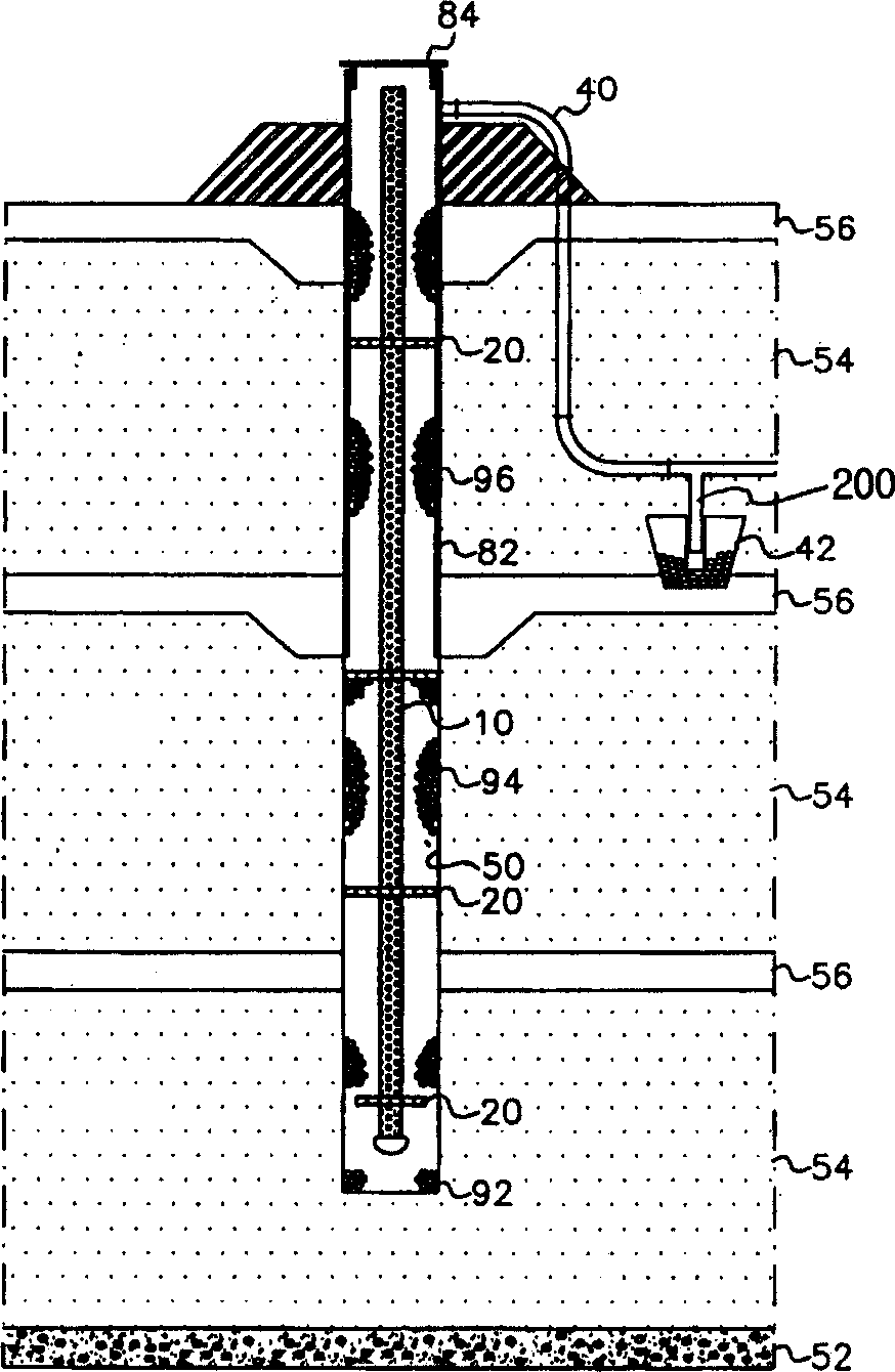
[0011] figure 1 is a diagram showing a gas discharge device installed in a landfill site according to an embodiment of the present invention. Such as figure 1 As shown, the leachate drainage layer 52 is located at the bottom of the landfill site, and at least one garbage layer 54 is formed on the leachate drainage layer 52 (in which the garbage is recycled to a predetermined height). Likewise, a cover soil layer 56 is located on the refuse layer 54, and the cover soil layer 56 is formed of a cover material such as soil or the like. A hole 50 is formed to a predetermined depth through the garbage layer 54 , and the gas collection pipe 10 is placed in the hole 50 . If possible, a spacer 20 and a steel pipe 82 may be further installed to maintain a gap between the garbage layer 54 a...


PUM


Abstract

A gas discharge device for a landfill site is disclosed having a condensate drain for removing condensate from hazardous and explosive gases generated in the landfill site. The gas discharge device at this landfill site includes: a gas collection pipe, located inside the garbage layer, to collect the gas generated by the garbage layer; a gas delivery pipe, connected to the upper part of the gas collection pipe, and to discharge the gas collected in the gas collection pipe ; and a condensate drain connected to the gas collecting pipe and separating the condensate from said gas by gravity, wherein the condensate drain comprises: a waterproof pipe having an opening in its upper portion; a porous pipe with the opening of the waterproof pipe and having a plurality of drainage holes in its side; and a connecting piece connecting the porous tube to the gas delivery tube in such a way that water can flow.

Description

technical field [0001] The present invention relates to a gas discharge device for a landfill site, and more particularly to a gas discharge device with a condensate drain for removing condensate from hazardous and explosive gases generated in a landfill site. Background technique [0002] Typically, waste (eg, municipal solid waste (MSW), construction waste, etc.) is reclaimed at landfill sites. In a landfill site, waste is recycled to a predetermined height, and the recycled waste is covered with a cover material such as soil (usually a "cover soil"). The process of recycling to landfill and covering is repeated several times, and the layers of recycled landfill waste are kept for years or decades to allow for natural decomposition. During the decomposition process, the decomposed litter layer produces flammable gases. The gases produced should be vented from the litter layer to reduce the potential for fires and explosions in the landfill site. In order to discharge ga...

Claims


Application Information

Patent Timeline
IPC IPC(8): B09B1/00F17D1/02F17D3/14
CPCB09B1/00B09B1/006Y02W30/30
Inventor 李和馥徐英锡金允熙郑用吉
Owner SUDOKWON LANDFILL SITE MANAGEMENT CORP
Why Eureka
Try Eureka