Visible-light response type automatic-bias photoelectrical catalytic water decomposition hydrogen production and electricity generation system

A photoelectric catalysis and visible light technology, applied in electrochemical generators, electrolysis processes, electrolysis components, etc., can solve the problems of low performance of photocatalytic water splitting for hydrogen production, limiting the full utilization of visible sunlight, and small self-bias voltage, etc. Visible light response and photocatalytic performance, realizing effective utilization, and improving the effect of self-bias

Inactive Publication Date: 2014-08-27
SHANGHAI JIAO TONG UNIV
View PDF6 Cites 9 Cited by
  • Summary
  • Abstract
  • Description
  • Claims
  • Application Information

AI Technical Summary

Problems solved by technology

However due to n-type WO 3 Constrained by the Fermi level of the electrode material, the self-bias voltage between the n-type electrode and the p-type electrode is still small, and the WO 3 The electrode material also has obvious photogenerated carrier recombination, these problems lead to the low performance of the pho

Method used


Image

  • Visible-light response type automatic-bias photoelectrical catalytic water decomposition hydrogen production and electricity generation system
  • Visible-light response type automatic-bias photoelectrical catalytic water decomposition hydrogen production and electricity generation system
  • Visible-light response type automatic-bias photoelectrical catalytic water decomposition hydrogen production and electricity generation system

Examples


preparation example Construction

[0031] The preparation method of the visible light-responsive self-bias photocatalytic water decomposition system for generating hydrogen and generating electricity includes the following specific steps:

[0032] 1) Preparation of the visible light-responsive Bi 2 S 3 Sensitized TiO 2 A nanotube array film electrode, the method is: firstly, the cleaned metal titanium plate is used as an anode, placed in an aqueous solution containing 0.5% hydrofluoric acid, the platinum electrode is used as a counter electrode, and the voltage is adjusted to 20V, and the metal titanium plate is Anodizing for 60 minutes to obtain TiO made of metal titanium and titanium surface 2 TiO 2 nanotube array material, then the titanium-based TiO 2 After the nanotube array material was sintered at 500°C for 1 hour, TiO with anatase phase was obtained 2 Nanotube array thin film material; with the TiO with anatase phase 2 The nanotube array thin film material is used as the substrate, and 0.5ml50mM B...

Embodiment 1

[0037] First, the cleaned metal titanium plate is used as an anode, placed in an aqueous solution containing 0.5% hydrofluoric acid, and the platinum electrode is used as a counter electrode to adjust the voltage to 20V, and the metal titanium plate is anodized for 60 minutes to obtain metal titanium and titanium Surface TiO 2 TiO 2 nanotube array material, then the titanium-based TiO 2 After the nanotube array material was sintered at 500°C for 1 hour, TiO with anatase phase was obtained 2 Nanotube array thin film material, based on the TiO with anatase phase 2 The nanotube array thin film material is used as the substrate, and 0.5ml50mM Bi(NO 3 ) 3 and 100mM Na 2 S solution, wherein the Bi(NO 3 ) 3 The solution uses 1M acetic acid solution as a solvent, and after each drop, it is coated at 3000rpm for 20s, and alternately repeated 30 times to obtain Bi 2 S 3 Sensitized Ti-based TiO 2 nanotube array thin film material, the Bi 2 S 3 Sensitized Ti-based TiO 2 The n...

Embodiment 2

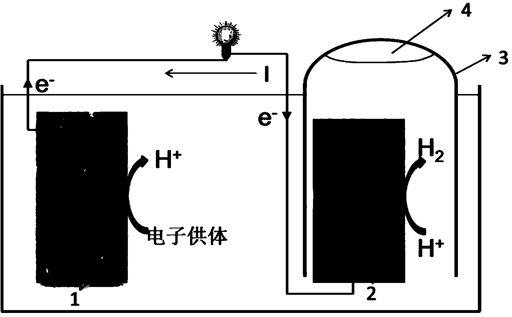
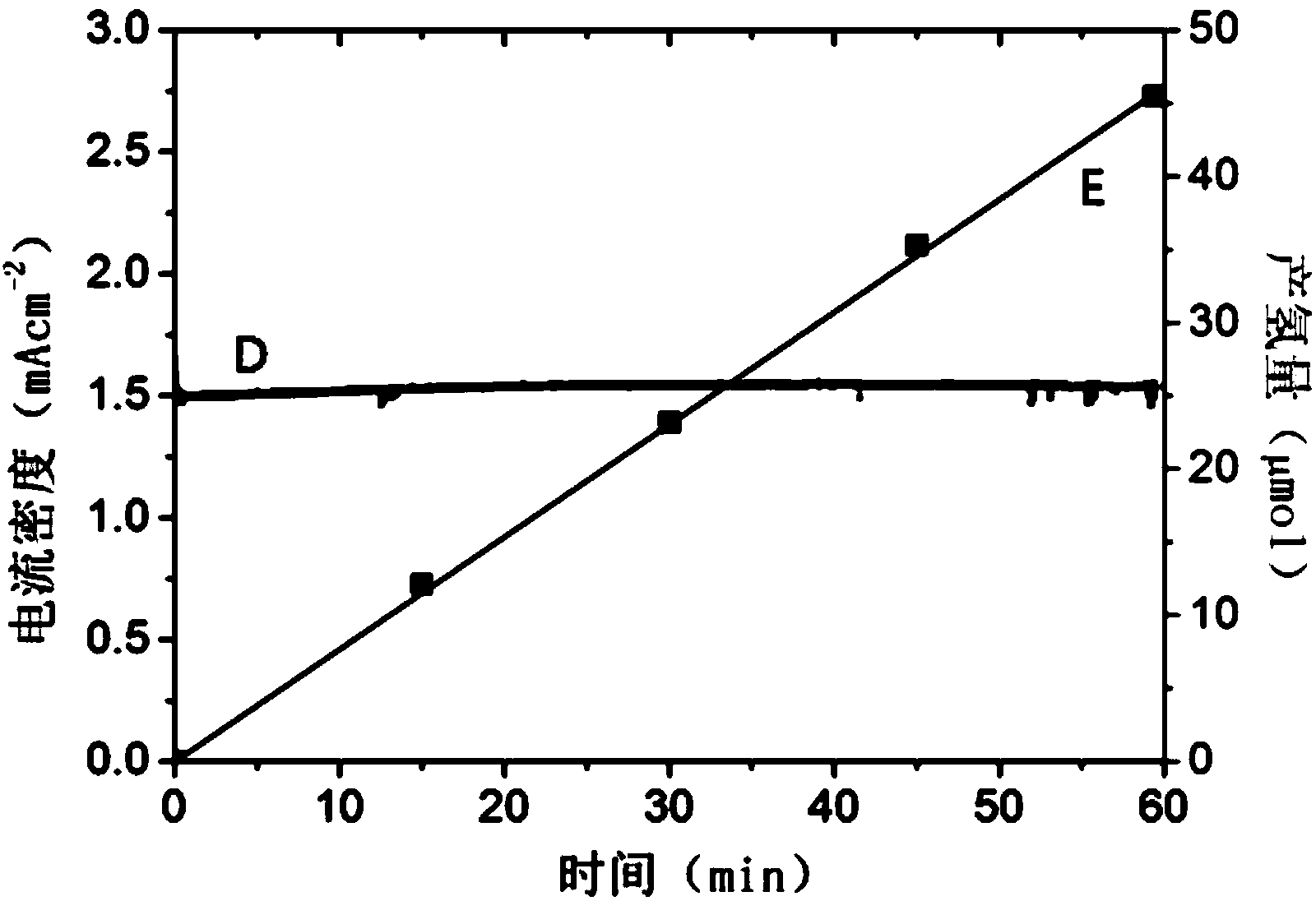
[0046] Bi in response to visible light 2 S 3Sensitized TiO 2 The nanotube array film electrode is used as the photoanode 1, and the visible light-responsive platinum-modified silicon cell electrode is used as the photocathode 2, respectively inserted with 0.1M Na 2 S electrolyte solution, and connected by external wires. Turn on the simulated sun light source (the light intensity is 100mW cm -2 ) irradiates the photoanode 1 and the photocathode 2, at this time the photogenerated electrons generated by the photocathode 2 convert the H in the electrolyte + Revert to H 2 , S in the electrolyte 2- On the photoanode 1, it is oxidized by the photogenerated holes, and the photogenerated electrons generated by the photoanode 1 are transmitted to the photocathode 2 through an external circuit and combined with the photogenerated holes, so as to realize photocatalytic hydrogen production and power generation at the same time. The hydrogen generation rate in this example is 43.1 μm...


PUM


Abstract

The invention provides a visible-light response type automatic-bias photoelectrical catalytic water decomposition hydrogen production and electricity generation system. The visible-light response type automatic-bias photoelectrical catalytic water decomposition hydrogen production and electricity generation system comprises a visible-light response type Bi2S3 sensitized TiO2 nanotube array film photo-anode, a visible-light response type silicon cell photo-cathode decorated with platinum, an electrolyte, a visible-light source, a quartz reaction tank and a quartz gas collecting tube. The materials of the photo-anode and the materials of the photo-cathode are both high in visible-light absorption performance. The photo-anode and the photo-cathode are inserted into a 0.1-0.5 M Na2S electrolyte solution at the same time and are connected through an external circuit. The visible-light source is switched on to irradiate the photo-anode and the photo-cathode, the photo-anode and the photo-cathode respectively generate an electrode reaction and then form a loop through the external circuit, and therefore automatic-bias photoelectrical catalytic hydrogen production and electricity generation are achieved. The invention further discloses a preparation method of the visible-light response type automatic-bias photoelectrical catalytic water decomposition hydrogen production and electricity generation system. The visible-light response type automatic-bias photoelectrical catalytic water decomposition hydrogen production and electricity generation system can be applied to solar hydrogen production and electricity generation at the same time and has the advantages of visible-light response, efficient hydrogen production and electricity generation, good stability and low cost. The visible-light response type automatic-bias photoelectrical catalytic water decomposition hydrogen production and electricity generation system and the preparation method of the system have an important significance in developing the solar hydrogen production and electricity generation technology.

Description

technical field [0001] The invention relates to a solar energy utilization system, in particular to a visible light-responsive self-bias photocatalytic system for decomposing water to produce hydrogen and generate electricity, belonging to the technical field of new energy. Background technique [0002] Due to the rapid development of the world economy, the human demand for energy is increasing day by day. However, the modern industry based on fossil energy is facing the fact that this non-renewable energy is about to be exhausted. Solar hydrogen production based on photoelectric catalysis is a promising new technology. The photoelectrocatalytic water splitting hydrogen production system is based on a double electrode. By introducing the photogenerated electrons or photogenerated holes of the photoelectrode to the counter electrode through an external circuit, the separation of the photogenerated charges is promoted, and the photoelectrocatalytic water splitting is realized...

Claims


Application Information

Patent Timeline
IPC IPC(8): H01L31/18H01L31/0224C25B1/02C25B11/06
CPCC25B1/02C25B11/051C25B11/077H01M8/0656Y02E60/50Y02P70/50
Inventor 周保学曾庆意黄可李雪瑾魏冉
Owner SHANGHAI JIAO TONG UNIV
Why Eureka
Try Eureka