
Fiber-optic grating sensor and fiber-optic grating detection device having same

A fiber grating and sensor technology, which is applied in the direction of measuring devices, using optical devices to transmit sensing components, instruments, etc., can solve the problems of small tuning range, inability to meet larger capacity multi-point detection, low resolution, etc., to improve the use of Power frequency voltage, solve the high voltage creepage problem, and improve the effect of detection accuracy

Inactive Publication Date: 2006-11-22
天津爱天光电子科技有限公司
View PDF8 Cites 12 Cited by
  • Summary
  • Abstract
  • Description
  • Claims
  • Application Information

AI Technical Summary

Problems solved by technology

The known fiber grating demodulation technology generally has the problems of small tuning range and low resolution, which cannot meet the needs of multi-point detection with larger capacity

Method used


Image

  • Fiber-optic grating sensor and fiber-optic grating detection device having same
  • Fiber-optic grating sensor and fiber-optic grating detection device having same
  • Fiber-optic grating sensor and fiber-optic grating detection device having same

Examples


Embodiment Construction

[0046] The specific implementation, structure, features and effects provided by the present invention will be described in detail below in conjunction with the accompanying drawings and preferred embodiments.

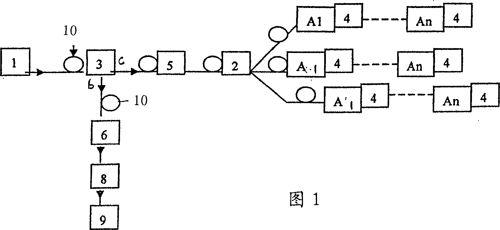
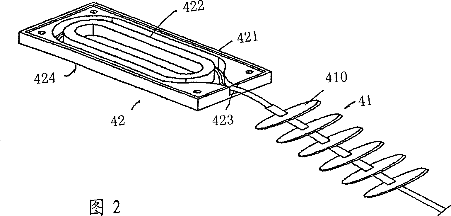
[0047] A large-capacity fiber grating temperature measuring device as shown in Figure 1-6, wherein,

[0048] An optical coupler or optical circulator 3, its first branch port is connected with broadband light source 1 through optical fiber 10; Its second branch port c is connected with standard fiber grating 5 through optical fiber;

[0049] The standard optical fiber grating 5 is connected to the common end of a 1×n optical switch 2, the branch port of the optical switch 2 is connected to each measurement channel, and each measurement channel is provided with a sensor group An, which is controlled by a preset The wavelength code is composed of 1-n fiber grating sensors 4 connected in series with different central wavelengths; thus, when a change in a certain reflection...


PUM


Abstract

The disclosed optical-fiber grating temperature measurer special to high-voltage power system comprises: an optical-fiber grating sensor, an optical coupler or optical ring device with the first-branch terminal connected to the broad-band optical source by fiber, the second-branch terminal connected to standard optical-fiber grating that connects with the public terminal of a 1*n optical switch with branch terminals linked to all measuring paths every with a sensor assembly, and the third-branch terminal connected to the demodulator with output end connected to a signal processing circuit.

Description

technical field [0001] The invention belongs to the technical field of optical fiber sensing, in particular to an optical fiber grating sensor used for temperature monitoring in a high-voltage power system and a temperature measuring device with the sensor. Background technique [0002] Power systems in high-voltage working conditions, such as substations, distribution stations or power supply, power generation systems, etc., are affected by many factors, such as the swing of equipment cables, power frequency vibration of electrical equipment, and equipment under humid environmental conditions. Under the action of work, construction or maintenance process defects and air oxidation, in the high-voltage main circuit of the equipment, the contact resistance of the equipment joint will gradually increase, so the surface of the joint will heat up, which will gradually increase the contact resistance and cause the temperature of the joint to rise. High vici...

Claims


Application Information

Patent Timeline
IPC IPC(8): G01D5/353G01K11/3206
Inventor 周大川干耀生郭转运董苏姗马林萍杜维
Owner 天津爱天光电子科技有限公司
Learn More