Auger-type refrigerating plant

A refrigeration device and screw-type technology, which is applied in the direction of rotary piston pumps, rotary piston machinery, refrigerators, etc., can solve the problems of reduced refrigeration capacity, insufficient sealing effect, and reduced performance of screw compressors, etc., to achieve improved refrigeration capacity , the effect of structural simplification

Inactive Publication Date: 2006-11-29
KOBE STEEL LTD
View PDF4 Cites 9 Cited by
  • Summary
  • Abstract
  • Description
  • Claims
  • Application Information

AI Technical Summary

Problems solved by technology

[0006] In the case of the above-mentioned Japanese Patent Application Laid-Open Report, JP 7-180917, JP 2000-179486, JP 2000-220893 and JP 2001-227830, especially in Japan In Japanese Patent Application Publication No. 2000-179486 and Japanese Patent Application Laid-Open No. 2000-220893, as clearly described as the shaft seal mechanism 1.8 or the shaft seal mechanism 1.9, between the penetrating motor and the screw compressor A shaft seal must be provided around the drive shaft of the next door to prevent leakage of refrigerant gas from the space inside the motor to the suction port of the screw compressor (the above motor is introduced with refrigerant flowing out of the economizer), so there is problems that complicate the structure
If the sealing effect of this part is insufficient, once the leakage of the above-mentioned refrigerant gas occurs, the performance of the screw compressor will be greatly reduced.
[0007] Moreover, in the case of the spiral refrigeration devices described in the above five patent documents, when a refrigerant in a liquid state is introduced into the motor, a large stirring loss will occur in the motor. Due to such a problem, it is necessary to Introduces the expanded gaseous refrigerant in the superheated state into the motor
As a result, the problem of so-called reduced freezing capacity

Method used


Image

  • Auger-type refrigerating plant
  • Auger-type refrigerating plant
  • Auger-type refrigerating plant

Examples


Embodiment Construction

[0021] Hereinafter, embodiments of the present invention will be described with reference to the drawings.

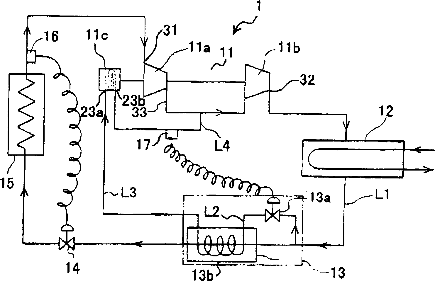
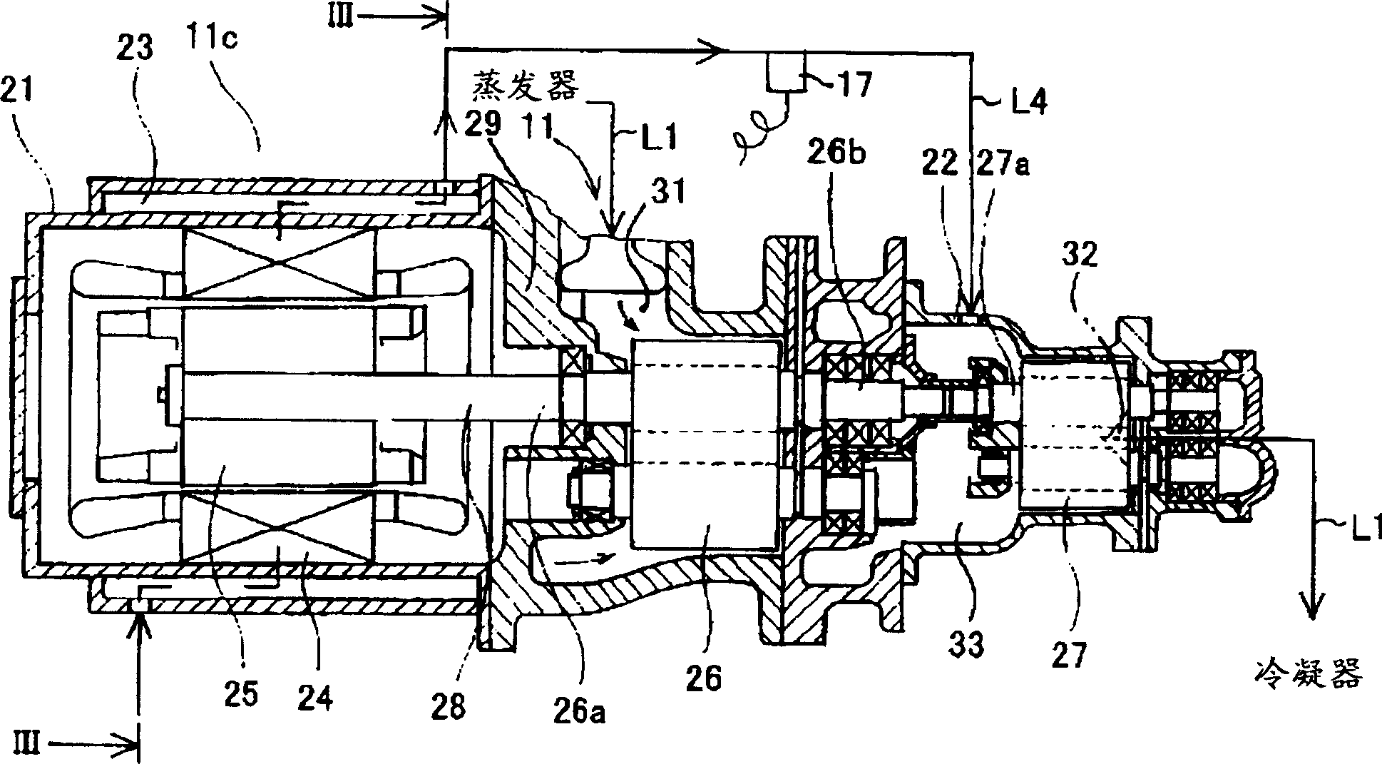
[0022] Figure 1 ~ Figure 3 The screw refrigeration device 1 showing the first embodiment of the present invention is provided with: a screw compressor 11, and the gas compression part is composed of a first-stage compressor main body 11a on the low-pressure stage side and a second compressor body 11a on the high-pressure stage side arranged in series. The stage compressor main body 11b constitutes, and a refrigerant circulation flow path L1 including a condenser 12 , an economizer 13 , a main expansion valve 14 and an evaporator 15 .

[0023] The so-called economizer is a mechanism that divides a part of the condensed and liquefied refrigerant, expands the refrigerant to the intermediate pressure between the condensation pressure and the evaporation pressure, and supercools the refrigerant.

[0024] The economizer 13 has an auxiliary expansion valve 13a and a heat exc...


PUM


Abstract

The spiral freezer of the invention includes a refrigerant cycle flow path comprising a screw compressor, a condenser, a heat-saving device, a main expansion valve and an evaporator, a heat-saving flow path in order to make refrigerant shunting from said cycle flow path move through supporting expansion valve 1 and then move through over-cooling flow path of the heat-saving device exchanging heat with refrigerant of the cycle flow path to inflow opening of double-pipe used for cooling the motor driving by the screw compressor, and a gas-cooling flow path from outflow opening of cooling jacket to the middle pressure department of the screw compressor. Thermal cones located on the gas-cooling flow path can detect temperature and accord to which to regulate the opening of the assisted expansion valve, so that the refrigerant becomes gas-liquid mixed state in the heat-saving flow path and the refrigerant becomes gas state in the gas-cooling flow path. Using said structures can simplify the structure and enhance the cooling capacity.

Description

technical field [0001] The invention relates to a spiral refrigeration device using a spiral compressor and an economizer. Background technique [0002] Previously, screw refrigeration plants using screw compressors and economizers have been known. [0003] In Japanese Patent Application Laid-Open No. 7-180917, a semi-hermetic spiral refrigeration device is disclosed. The refrigerant cooled by the economizer is introduced between the suction port and the discharge port in the spiral compressor, and The intermediate pressure section not connected to the suction port and the discharge port in the screw compressor, on the other hand, will start from the economizer, pass through the first expansion valve, and reach the refrigerant circulation flow path of the evaporator at the The refrigerant branched before the first expansion valve passes through another second expansion valve, is introduced into a motor that drives the screw compressor, passes through the motor, and is intro...

Claims


Application Information

Patent Timeline
Patent Type & Authority Applications(China)
IPC IPC(8): F25B1/047
CPCF25B2400/13F25B2600/2509F04C18/16F04C28/24F04C29/042F04C29/124F04C2210/26F25B31/006F25B49/022Y10S415/00Y10S417/00
Inventor 壶井升
Owner KOBE STEEL LTD
Why Eureka
Try Eureka