
Backlight module set

A backlight module and light source technology, applied in optics, nonlinear optics, instruments, etc., can solve the problems of reducing the utilization rate of light energy and affecting the uniformity of light emission of the backlight module 30, and achieve the effect of uniform light emission

Inactive Publication Date: 2006-12-06
HONG FU JIN PRECISION IND (SHENZHEN) CO LTD +1
View PDF0 Cites 3 Cited by
  • Summary
  • Abstract
  • Description
  • Claims
  • Application Information

AI Technical Summary

Problems solved by technology

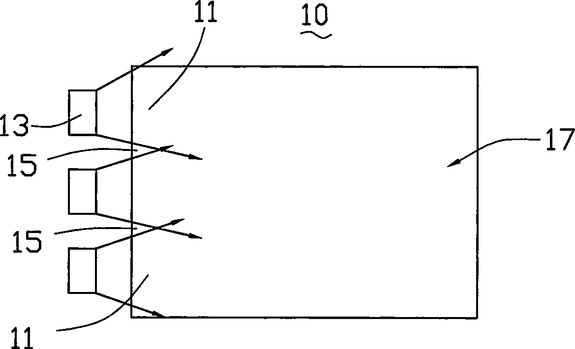
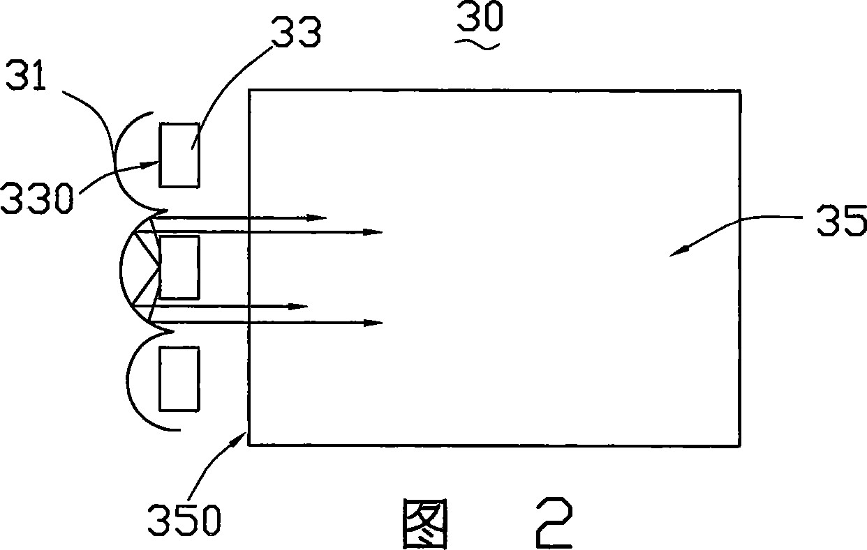
This structure has a certain effect on eliminating dark bands, but since the reflector 31 is arc-shaped, the LED light source 33 will block part of the light reflected back from the reflector 31, which is easy to form on the light guide plate 35 behind the multiple LED light sources 33. A small shadow area, thereby affecting the uniformity of light emission of the backlight module 30 and reducing the utilization rate of light energy

Method used


Image

  • Backlight module set
  • Backlight module set
  • Backlight module set

Examples


Embodiment Construction

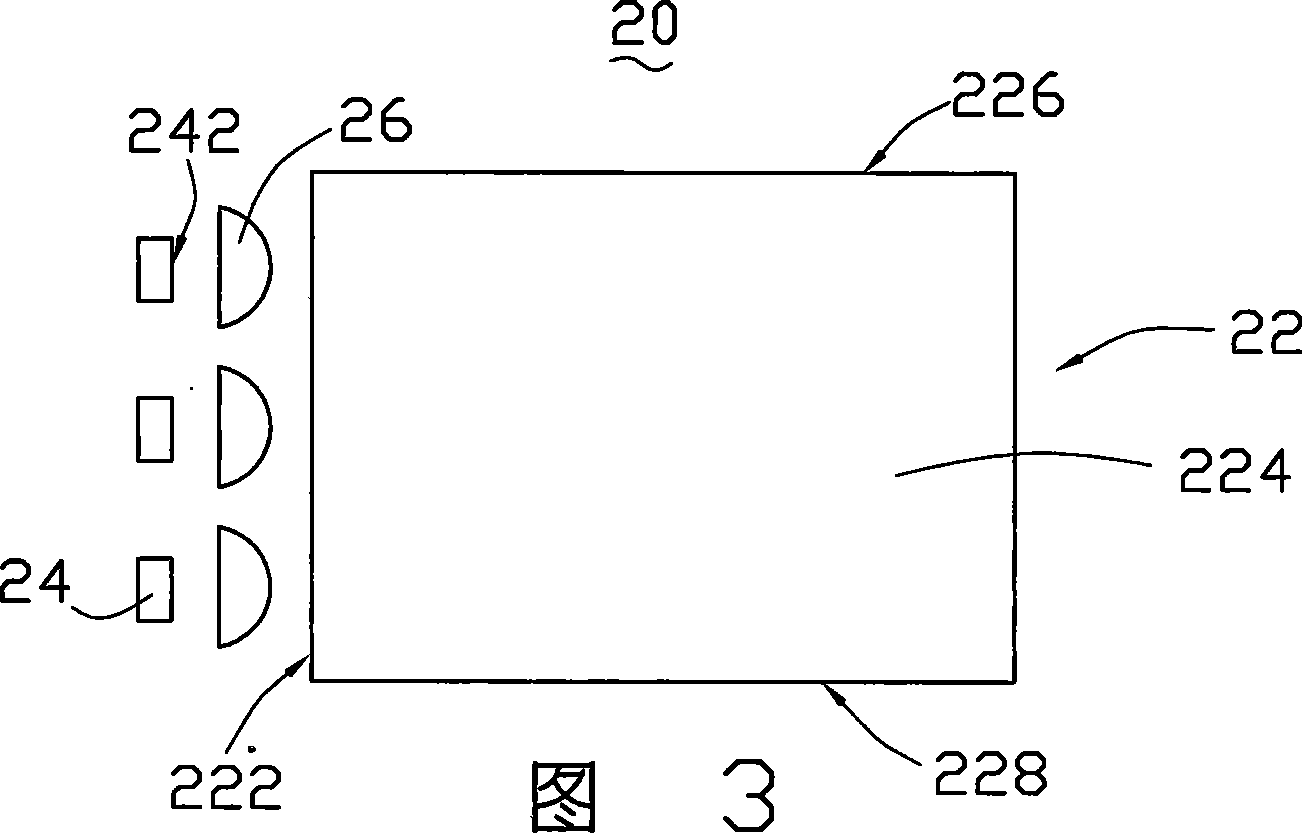
[0016] Please refer to Figure 3 and Figure 4 , the first embodiment of the present invention provides a backlight module 20, the backlight module 20 includes a light guide plate 22, three LED light sources 24 arranged on one side of the light guide plate 22 and three LED light sources 24 arranged between the light source 24 and the light guide plate 22 Cylindrical mirror 26.

[0017] The light guide plate 22 includes a light incident surface 222, a light exit surface 224 connected to the light incident surface 222, a bottom surface (not shown) opposite to the light exit surface 224, and two side surfaces 226 adjacent to the light incident surface 222, 228.

[0018] The light source 24 is located on one side of the light incident surface 222 , and the light source 24 has a light emitting surface 242 facing the light incident surface 222 .

[0019] The light emitted by the light source 24 is incident on the light incident surface 222 of the light guide plate 22 through the cy...


PUM


Abstract

The invention supplies a backlight module includes a light guiding board, at least a light resource. A light intake surface, a light emitting surface and a bottom are included into the light guiding board. The backlit module at least includes a cylindrical mirror between light resource and light guiding board.

Description

【Technical field】 [0001] The invention relates to a backlight module, in particular to a side-mounted backlight module. 【Background technique】 [0002] Since the liquid crystal display is a non-luminous display device, a backlight module is required to produce a display function. The performance of the backlight module often directly affects the image quality of the display. Therefore, the backlight module becomes the most important component in the liquid crystal display. The so-called side-mounted backlight module means that the light source is arranged on one side of the light guide plate, and the light beam enters the light guide plate from the side and continuously propagates forward in the light guide plate. Displays with side-mounted backlight modules are widely used in fields such as notebook computers, vehicle displays, and mobile communications due to their small size and light weight. [0003] The light source of the backlight module can be a cold cathode fluore...

Claims


Application Information

Patent Timeline
Patent Type & Authority Applications(China)
IPC IPC(8): G02F1/1335
Inventor 邱文赐
Owner HONG FU JIN PRECISION IND (SHENZHEN) CO LTD
Learn More