
Method for controlling impedance

An impedance control, vertical direction technology, applied in the field of communication, can solve the problem that the impedance value cannot be continuously selected and determined arbitrarily, and achieve the effect of improving the transmission quality, the method is simple, and the widespread promotion

Active Publication Date: 2006-12-06
XFUSION DIGITAL TECH CO LTD
View PDF0 Cites 14 Cited by
  • Summary
  • Abstract
  • Description
  • Claims
  • Application Information

AI Technical Summary

Problems solved by technology

Therefore, with this impedance control method, the impedance value cannot be determined arbitrarily continuously

Method used


Image

  • Method for controlling impedance
  • Method for controlling impedance
  • Method for controlling impedance

Examples


Embodiment Construction

[0029] Below according to accompanying drawing and embodiment the present invention will be described in further detail:

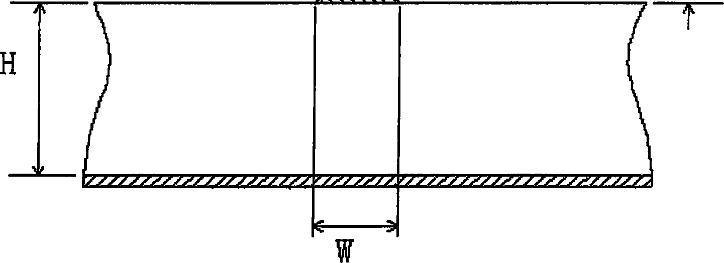
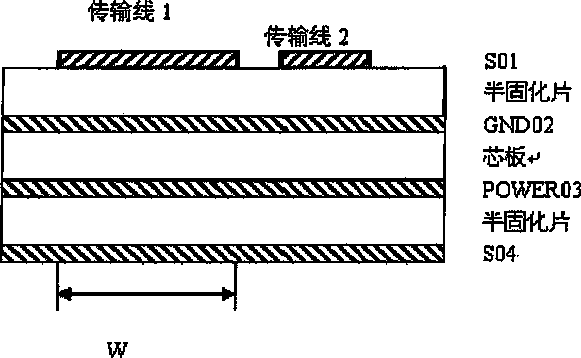
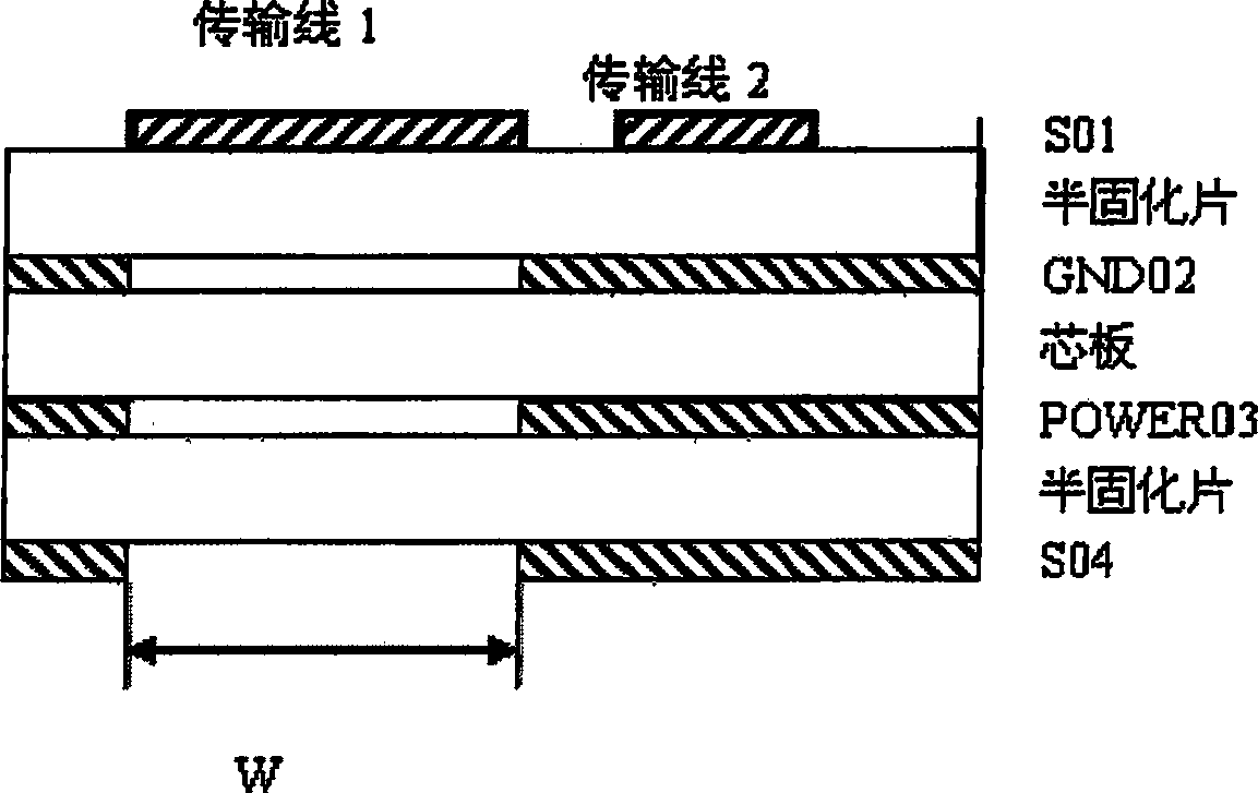
[0030] by Figure 2a , Figure 2b The four-layer veneer shown is taken as an example, and the stacked structure of the veneer is as follows image 3 As shown, the first layer is the signal layer 1, the second layer is the GND plane layer, the third layer is the POWER plane layer, and the fourth layer is the signal layer 2; Parts are made of media. Both transmission line 1 and transmission line 2 are located on the first layer of the board, and the width of transmission line 1 is greater than that of transmission line 2. Transmission line 1 can be a single line, a differential line, a pad of a device, etc. We assume that transmission line 1 is a pad of a matching device ;for Figure 2a In the prior art situation shown, the reference plane of the S1 layer signal is the GND layer. According to formula 1, it can be seen that since the pad of the matching d...


PUM


Abstract

The method comprises: a) hollowing out all signaling layers and plane-layers corresponding to the vertical direction of the controlled transmission line; b) the hollowed widths of all signaling layers and plane-layers can be set into a variable; with adjusting and setting the hollowed width, controlling the impedance of transmission line at any required values.

Description

technical field [0001] The invention relates to the technical field of communication, in particular to a method for controlling the impedance of a transmission line of a high-speed printed circuit board. Background technique [0002] As the operating frequency of the chip is getting higher and higher, the rise time of the signal is getting faster and faster, which will be a great challenge to the design of the printed circuit board. On the current single board, the signal frequency has reached 10Gbps, even higher 40Gbps, and the rise time is only tens of picoseconds. How to realize the design through the printed circuit board needs to be considered in the early stage of the printed circuit board design. The problem. [0003] Impedance control is the most basic requirement for the realization of high-speed printed circuit boards, especially in high-speed multilayer boards, and is also a method often used in printed circuit board design. Usually, impedance control is achieved...

Claims


Application Information

Patent Timeline
IPC IPC(8): H05K3/00H05K3/46H05K1/02H04B3/04
Inventor 唐晟刘卫东何波
Owner XFUSION DIGITAL TECH CO LTD
Learn More