Heat exchanger, especially charge-air/coolant radiator

A technology of heat exchanger and charge air, which is applied in the direction of heat exchange equipment, heat exchanger type, heat exchanger shell, etc., and can solve the problem of unsatisfactory cooling efficiency of charge air/coolant cooler

Inactive Publication Date: 2006-12-06
BEHR GMBH & CO KG
View PDF0 Cites 0 Cited by
  • Summary
  • Abstract
  • Description
  • Claims
  • Application Information

AI Technical Summary

Problems solved by technology

But the cooling efficiency of this charge a

Method used


Image

  • Heat exchanger, especially charge-air/coolant radiator
  • Heat exchanger, especially charge-air/coolant radiator
  • Heat exchanger, especially charge-air/coolant radiator

Examples


Embodiment Construction

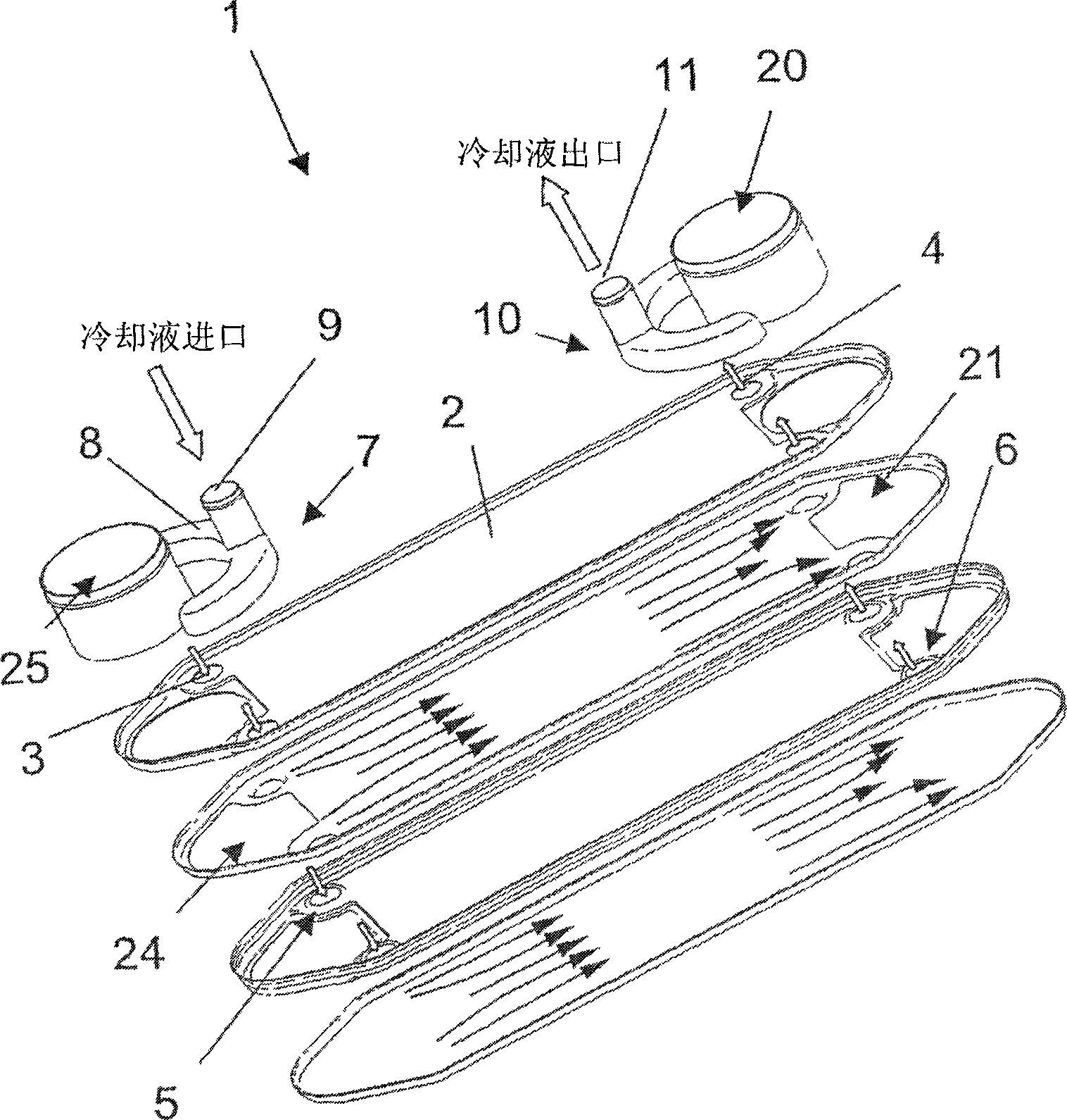
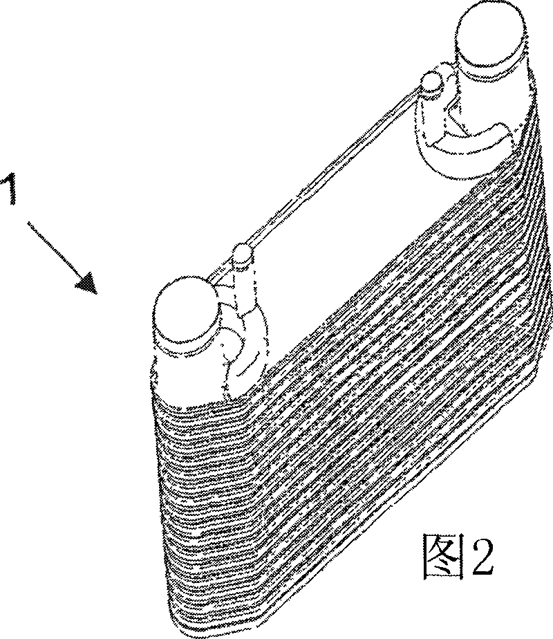
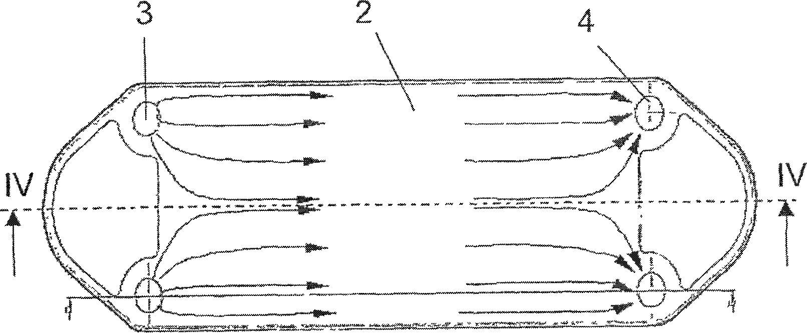
[0025] As shown in the figure, the charge air / coolant cooler 1 as a heat exchanger between the charge air and the coolant has a plurality of coolant pans 2 stacked on top of each other. Here, two inflow holes 3 and two outflow holes 4 are respectively provided in each cooling liquid pan 2 , through which the cooling liquid as a heat exchange medium enters the gap in the middle of the cooling liquid pan 2 or flows out there. The direction of flow is indicated by arrows in the figure. After the coolant enters through the inflow hole 3, it spreads in the entire width of the gap in the middle of the coolant plate 2, and evenly flows to the outflow hole 4 (see image 3 ), so that the entire length and width of the intermediate space between the inlet hole 3 and the outlet hole 4 is flowed through, so that the charge air / coolant cooler 1 between the coolant pans 2, The heat transfer of the charge air to be cooled is optimized.

[0026] The holes 3 and 4 in the coolant tray 2 place...


PUM


Abstract

Disclosed is a heat exchanger, particularly a charge-air/coolant radiator (1), having a disk-type structure. Said heat exchanger comprises a plurality of disks (2) which are penetrated by a coolant and a fluid that is to be cooled. The inlet zone and/or outlet zone for the fluid that is to be cooled is/are expanded at least at the discharge end or delivery end.

Description

technical field [0001] The invention relates to a heat exchanger with a disc structure, in particular a charge air / coolant cooler. Background technique [0002] In a conventional plate-shaped charge air / coolant cooler, the charge air and coolant enter the coolant plate via a single connection with a circular cross section. However, the cooling efficiency of this charge air / coolant cooler is still not satisfactory. Contents of the invention [0003] It is an object of the present invention to provide an improved heat exchanger. [0004] This object is achieved by a heat exchanger having the following characteristics. Further features provide advantageous embodiments. [0005] According to the invention, a heat exchanger, in particular a charge air / coolant cooler, has a disc design, wherein two adjacent discs define an intermediate space which is filled by a heat exchange medium, in particular a A cooling liquid, preferably a mixture of water and glycol (Glykol), flows t...

Claims


Application Information

Patent Timeline
IPC IPC(8): F28D9/00F28F27/02
CPCF28D9/005F28F9/026F28D2021/0082F28D2021/0089
Inventor 丹尼尔·亨德里克斯弗洛里安·莫尔多万于尔根·弗格纳
Owner BEHR GMBH & CO KG
Why Eureka
Try Eureka