Lens driver

A lens driving device, lens technology, applied in the direction of beam guiding device, installation, optics, etc., to achieve the effect of simple positioning and improved impact resistance

Inactive Publication Date: 2009-11-25
COPAL CO LTD
View PDF3 Cites 4 Cited by
  • Summary
  • Abstract
  • Description
  • Claims
  • Application Information

AI Technical Summary

Problems solved by technology

In the past, it was difficult to resolve such conflicting issues

Method used


Image

  • Lens driver
  • Lens driver
  • Lens driver

Examples


no. 1 approach

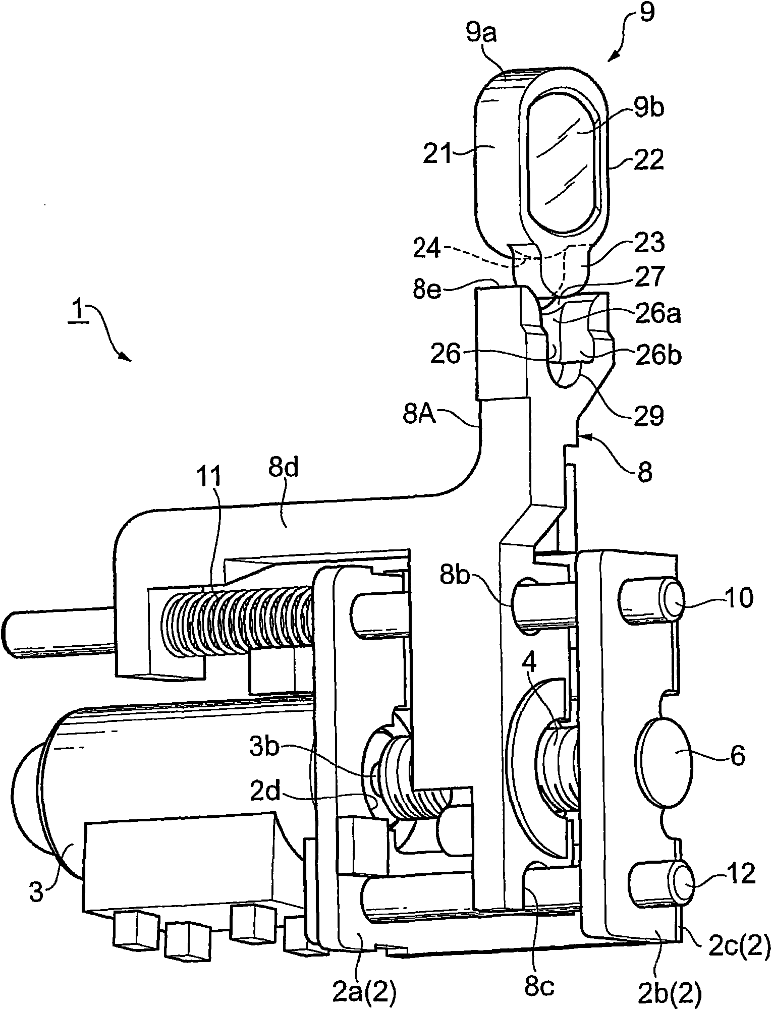
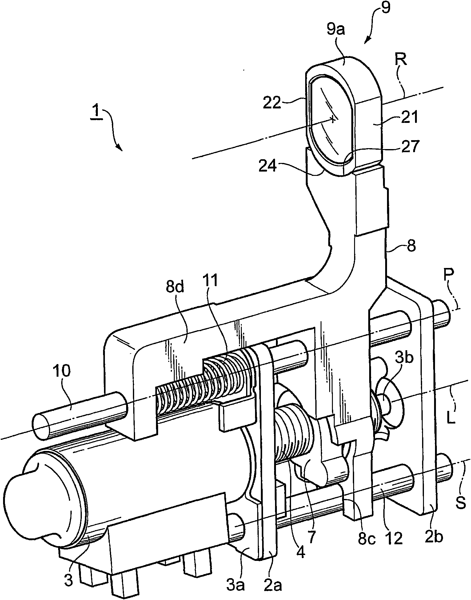
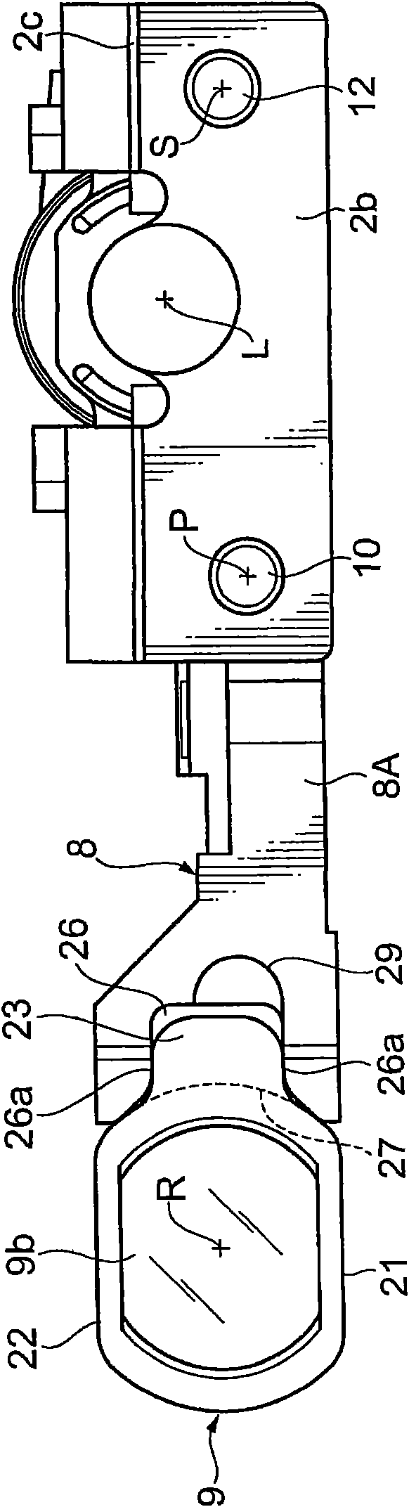
[0042] In the optical pickup mechanism (optical part) inside the optical disc device, it is necessary to accurately converge the light beam on the information layer of the optical disc. Therefore, in a high-precision optical pickup mechanism, in order to be able to compensate for the spherical aberration caused by the thickness error of the cover layer of the optical disc, the lens needs to be slightly moved along the optical axis direction.

[0043] Such as Figure 1 ~ Figure 4 As shown, the lens driving device 1 mounted on the optical pickup mechanism (optical part) is used for spherical aberration compensation of the lens, and has a base member 2 in the shape of "U". The base members 2 have mutually parallel In order to realize the unitization of the two frame bodies 2a, 2b and the bottom plate 2c, the following components are assembled on the base member 2.

[0044]The stepping motor 3 is fixed to the frame body 2a via the bracket 3a, and the lead screw 4 is fixed to the rotati...

no. 2 approach

[0063] In the lens driving device 1 of this embodiment, the same components as those in the first embodiment described above are denoted by the same reference numerals, and repeated descriptions are omitted. In addition, the reference numeral 108 is attached to the lens and the reference numeral 109 is attached to the lens holder for the following description.

[0064] Figure 8 It is a perspective view showing the second embodiment of the lens driving device of the present invention. The base member 2 in the second embodiment has basically the same structure as the base member 2 in the first embodiment, but there are differences as described below. In the second embodiment, the compression coil spring 11 is wound around the rotation stop shaft 12. In addition, a hole for inserting the anti-rotation shaft 12 is formed at the end of the lens holder 108, and the anti-rotation shaft 12 penetrates the compression coil spring 11 so that the compression coil spring 11 is arranged betwe...


PUM


Abstract

The invention provides a lens driver mounted on an optical part, comprising a leading screw rotating by utilizing the rotating of a motor, a lens carrier reciprocating along the a rotational axis leading screw by utilizing the rotating of the leading screw, a leading axle extending in parallel to the rotational axis and penetrating the lens carrier and guiding the lens carrier, and a lens mounted on the free end of the lens carrier in the cantilevering state. Thereby, in the lens driver, a part of frame part for forming the lens carrier is removed around the lens, thus the lens face can be big as far as possible.

Description

Technical field [0001] The present invention relates to a lens driving device that is installed in an optical unit (for example, an imaging unit of a portable terminal device or an optical pickup mechanism of an optical disc device) for focusing of a lens or compensation for spherical aberration of the lens. Background technique [0002] The optical pickup device described in Japanese Patent Application Laid-Open No. 2006-114117 has a lens drive device for compensation of the spherical aberration of the lens. The lens drive device is connected to a movable The rack part on the lens holder engages, so that the lens holder advances and retreats along the optical axis. A circular opening is provided in the lens holder, and the lens is fixed in the opening. [0003] However, there is a frame part that becomes a part of the lens frame around the opening part provided on the lens holder. Therefore, the size of the lens has to be reduced according to the frame part. On the contrary, the...

Claims


Application Information

Patent Timeline
Patent Type & Authority Applications(China)
IPC IPC(8): G02B7/02G02B7/04G11B7/135G11B7/0037
Inventor 大江晴树石政徹藤村洋二渡部研一
Owner COPAL CO LTD
Why Eureka
Try Eureka