
Exhaust gas treatment apparatus and exhaust gas treatment method for internal combustion engine

An exhaust gas treatment device and a technology for exhaust gas treatment, which are applied to the electronic control of the exhaust gas treatment device, the diagnosis device of the exhaust gas treatment device, and the exhaust device, etc., can solve the problem of ineffective catalytic converter purification performance, etc. Reduce the effect of inhibition

Inactive Publication Date: 2016-10-05
TOYOTA JIDOSHA KK
View PDF7 Cites 4 Cited by
  • Summary
  • Abstract
  • Description
  • Claims
  • Application Information

AI Technical Summary

Problems solved by technology

As a result, the exhaust gas passing through the conical member flows into only a part of the catalytic converter without much diffusion, and the purification performance of the catalytic converter cannot be effectively maximized.

Method used


Image

  • Exhaust gas treatment apparatus and exhaust gas treatment method for internal combustion engine
  • Exhaust gas treatment apparatus and exhaust gas treatment method for internal combustion engine
  • Exhaust gas treatment apparatus and exhaust gas treatment method for internal combustion engine

Examples


Embodiment Construction

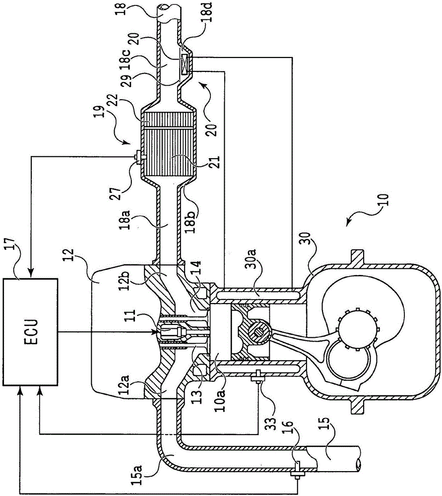
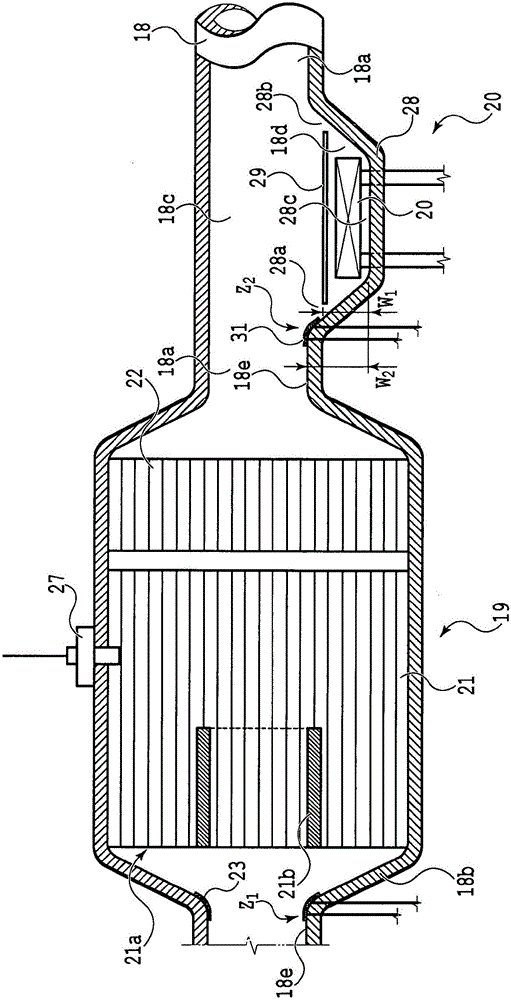
[0063] refer to Figure 1 to Figure 9 One embodiment in which the disclosure of the present application is applied to a vehicle equipped with a compression ignition multi-cylinder internal combustion engine will be described in detail. However, the disclosure of the present application is not limited to such an embodiment, and the structure disclosed in the present application can be freely changed according to the required characteristics. For example, the disclosure of the present application is also effective for an internal combustion engine of a spark ignition system that uses gasoline, alcohol, LNG (liquefied natural gas) or the like as fuel and ignites the fuel with a spark plug.

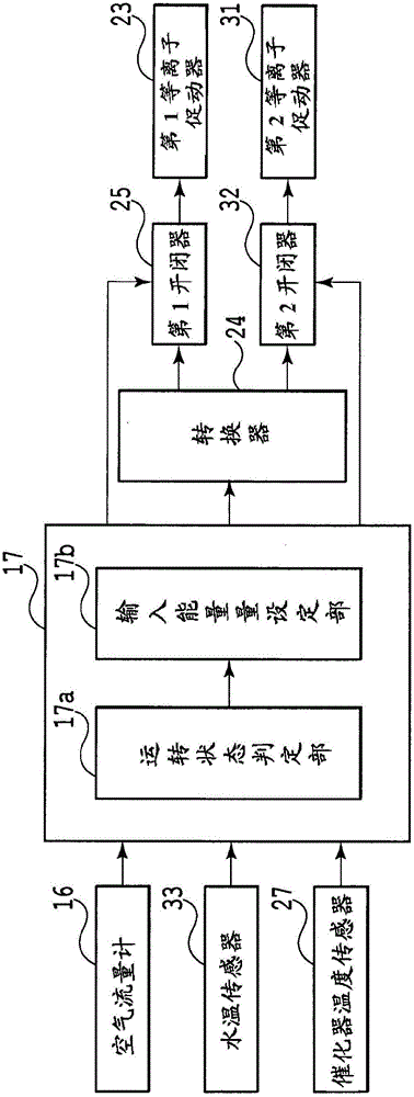
[0064] exist figure 1 The main part of the engine system in this embodiment is schematically shown in figure 2 The control frame of the above-mentioned main part is roughly represented in . In addition, in figure 1 In FIG. 2 , as an auxiliary machine of the engine 10 , a general exhaust ...


PUM


Abstract

When a louver member able to diffuse exhaust gas over the entire area of a catalytic converter is incorporated in the exhaust passage, passage resistance of the exhaust gas increases and, in addition, the time to complete a warm-up of the internal combustion engine is extended, and this leads to deterioration of fuel economy. An exhaust gas treatment apparatus for an internal combustion engine includes an exhaust gas treatment unit (21, 22) arranged in an exhaust passage (18a) of the engine (10), an exhaust gas burble zone (Z1, Z2) in which an exhaust gas flowing along a part of a wall face (18e), which defines the exhaust passage, burbles away from the part of the wall face, and a plasma actuator (23, 31) arranged at the part of the wall face of the exhaust passage in the exhaust gas burble zone and configured to generate air current toward the exhaust gas treatment unit along the part of the wall face.

Description

technical field [0001] The invention relates to a device and a method for treating exhaust gases from an internal combustion engine. Background technique [0002] When the vehicle is intended to be downsized, the installation space of auxiliary equipment mounted on the vehicle is limited, and various piping paths and the like have to be greatly buckled. For example, since the exhaust turbine of the supercharger, the catalytic converter of the exhaust purification device, the muffler, etc. are closely arranged in the exhaust passage that guides the exhaust gas exhausted from the internal combustion engine mounted on the vehicle, so the connection Exhaust pipes of these components require substantial buckling. [0003] In addition, the passage cross-sectional area of ​​the catalytic converter of the exhaust gas purification device sometimes reaches several times the passage cross-sectional area of ​​the exhaust pipe in order to improve the purification efficiency of exhaust g...

Claims


Application Information

Patent Timeline
Patent Type & Authority Applications(China)
IPC IPC(8): F01N13/08F01N3/035F01N13/14
CPCF01N3/035F01N13/082F01N13/14F01N2240/28H05H1/2406F01N3/0892F01N3/10F01N3/103F01N3/2889F01N5/02F01N9/00F01N13/08F01N13/1833F01N3/021F01N2240/02F01N2240/20F01N2250/02F01N2330/60F01N2560/06F01N2560/07F01N2900/1411F01N2900/1602F01N13/0097Y02T10/12Y02T10/40F01N3/2892F01N11/002F01N13/143F01N2550/02F01P2025/08
Inventor 山本孝祐
Owner TOYOTA JIDOSHA KK
Learn More