Method for operating a network

A network and network interface technology, applied in the field of operational network, can solve the problems of reducing network transmission capacity and inapplicability, and achieve the effect of increasing equipment complexity, reducing device requirements and power consumption

Active Publication Date: 2006-12-06
SIEMENS AG
View PDF2 Cites 3 Cited by
  • Summary
  • Abstract
  • Description
  • Claims
  • Application Information

AI Technical Summary

Problems solved by technology

The disadvantage is that the test telegrams transmitted via the redundancy manager to the two line ends constitute an additional load on the network and thus reduce the transmission capacity of the network
In addition, in some bus systems, while ...

Method used


Image

  • Method for operating a network
  • Method for operating a network
  • Method for operating a network

Examples


Embodiment Construction

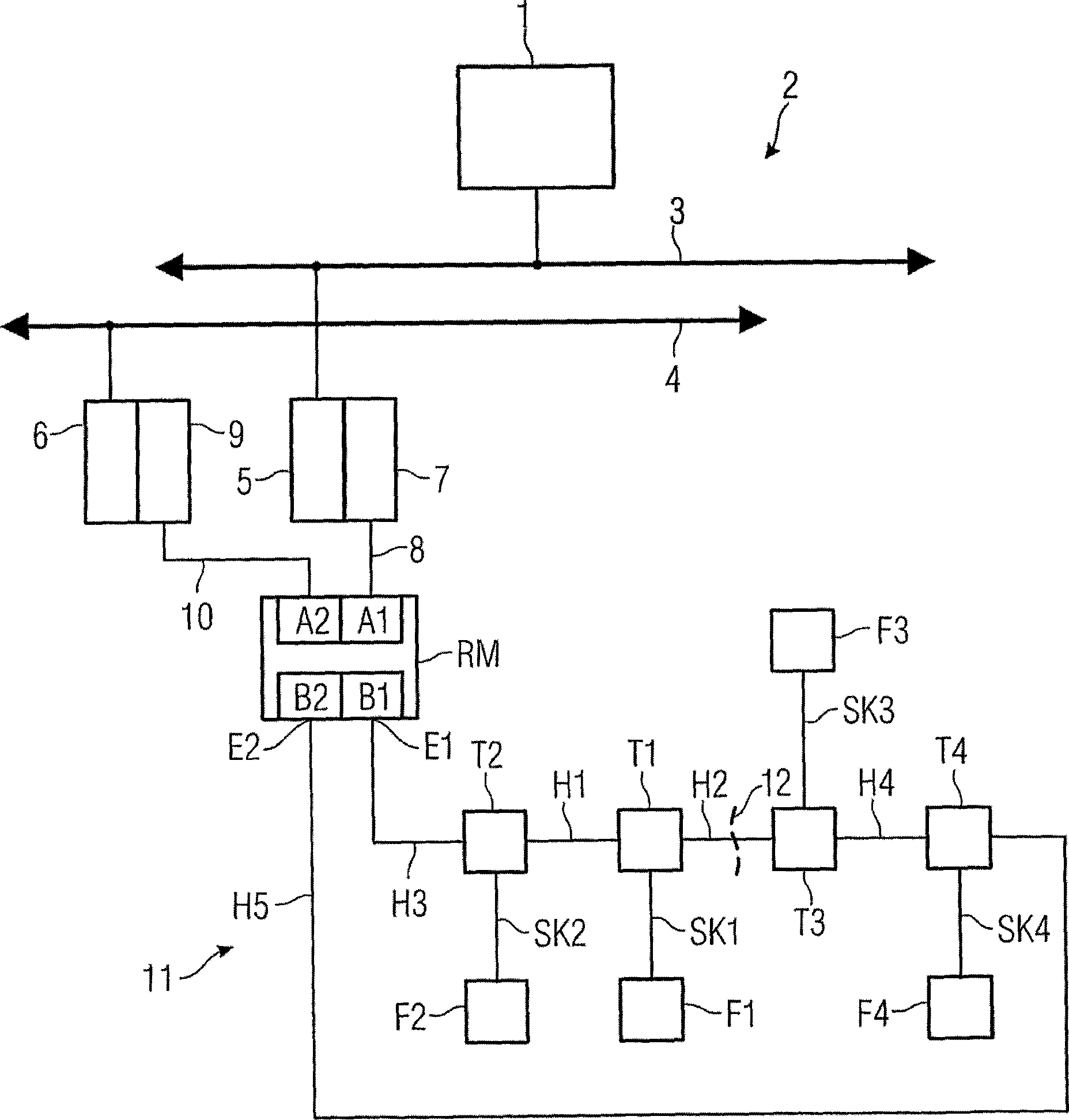
[0026] figure 1 Shown is a part of an automation technology device. A control system 1 is connected to the bus system 2 according to the distributed peripheral fieldbus standard. The bus system 2 can be of simple design or as figure 1Redundant design shown. To each communication channel 3 , 4 of the bus system 2 is connected a link 5 or 6 respectively, in addition to other devices, such as automation devices (not shown in the figure). The link 5 is connected to a segment connector 7 which is connected via a branch cable 8 to a port A1 of a redundancy manager RM. Another link 6 is connected to another segment connector 9 which is connected via another branch cable 10 to a port A2 of the redundancy manager RM. The other two ports B1 and B2 of the redundancy manager RM are connected to a network 11 which conforms to the process automation fieldbus standard and has a line topology. A line end E1 of the network 11 is formed by the end of a trunk cable H3 connected to the port ...


PUM


Abstract

The invention relates to a network, in particular to a PA PROFIBUS network having redundant properties and a linear topology. Two line ends (E1, E2) are connected to a redundancy manager (RM) which disconnects said line ends (E1, E2) in error-free conditions and connects them in error conditions. Said redundancy manager (RM) supplies voltage to the first line end (E1) for operating customers' mobile telephones (Fi-F4) each of which is connected to the network (11) by a branching unit (T1-T4). After receiving a supply voltage on one connection thereof, said branching units (T1-T4) check the state of a cable (H1-H5) which is connected to the other network connection and transmit the supply voltage in the faultless condition thereof only. When the redundancy manager (RM) does not detect the supply voltage on the other end of the line end (E2) at least during a predetermined space of time after voltage supply, said redundancy manager supplies the voltage thereto. A cable (H2) having a disturbance (12) is then disconnected from the line by the adjacent branching units (T1-T3).

Description

technical field [0001] The present invention relates to a redundant network described in the preamble of claim 1, in particular to a PROFIBUS PA-Netzwerk (process automation field bus network), a network described in the preamble of claim 8, with Tributary units of user equipment in said network, a redundancy manager for said network according to the preamble of claim 13, and a system according to the preamble of claim 17 of said network described method of operation. Background technique [0002] In automation technology process plants with wiring of "conventional" field devices, such as measuring transducers and / or control mechanisms, the field devices are routed via four-wire backbone cables and junction boxes with the aid of an own core pair And respectively connected with a programmable controller, because each field instrument works in the case of physical separation from each other, therefore, even if one of the field instruments fails or the transmission line leadin...

Claims


Application Information

Patent Timeline
IPC IPC(8): G05B19/048H04L12/26
Inventor 霍尔格·弗曼弗里德赫尔姆·盖格格哈德·哈默克劳斯·罗瑟
Owner SIEMENS AG
Why Eureka
Try Eureka